- Purchased: 2024
- Completed: 2026
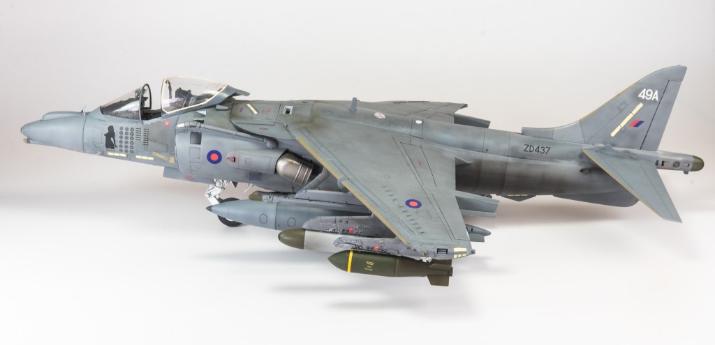
- Enhancements
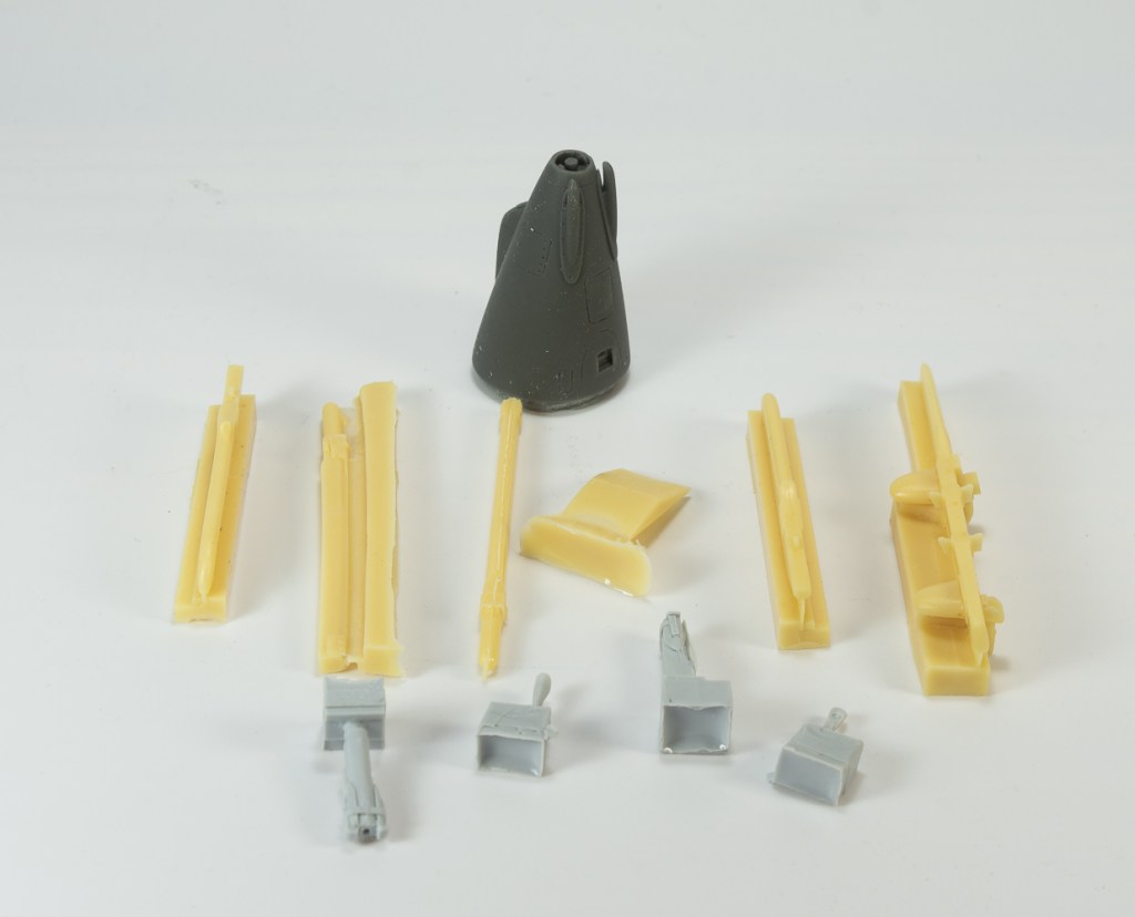
- Seats, – Brassin
- Exhausts – Quickboost
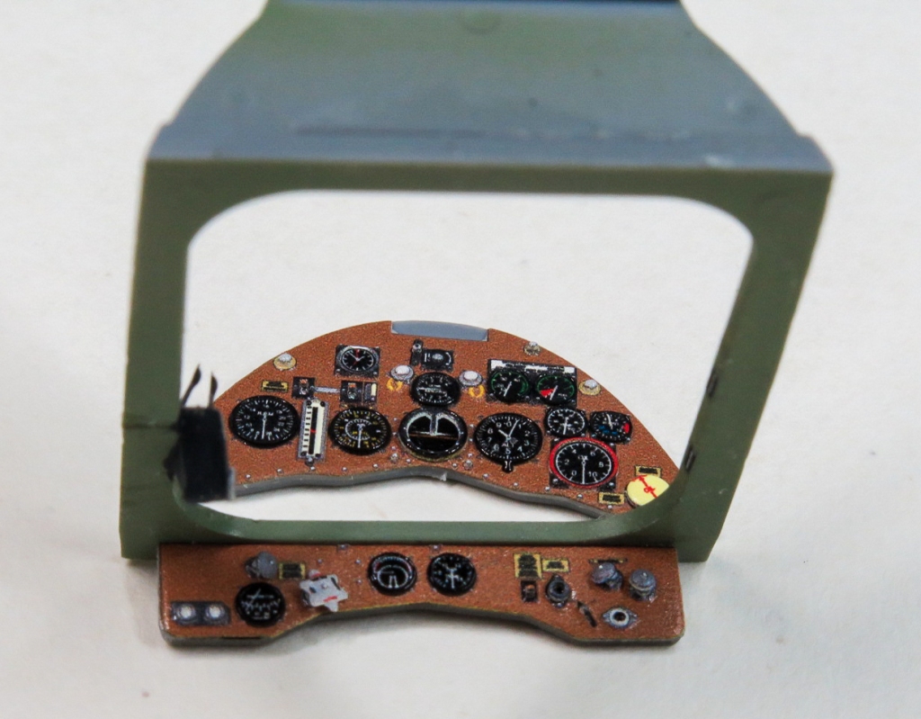
- Instrument panel and seatbelts – Eduard
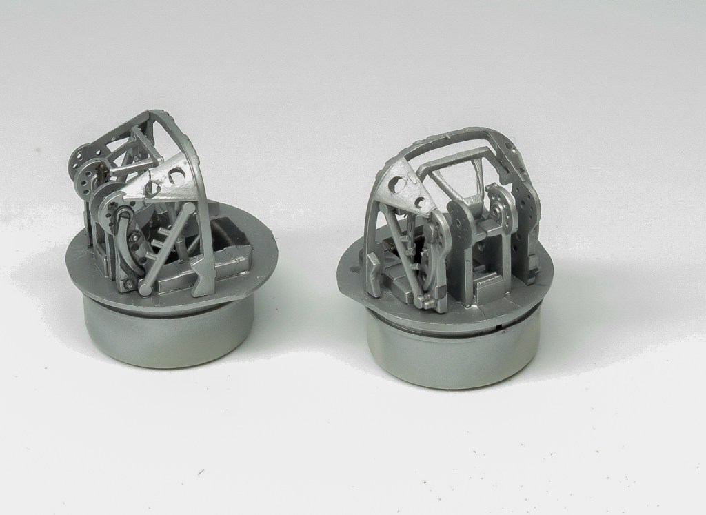
- Wheels – Eduard
- Decals – custom made masks
Introduction
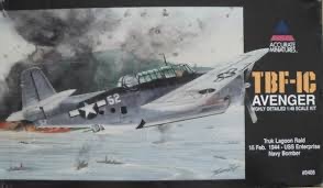
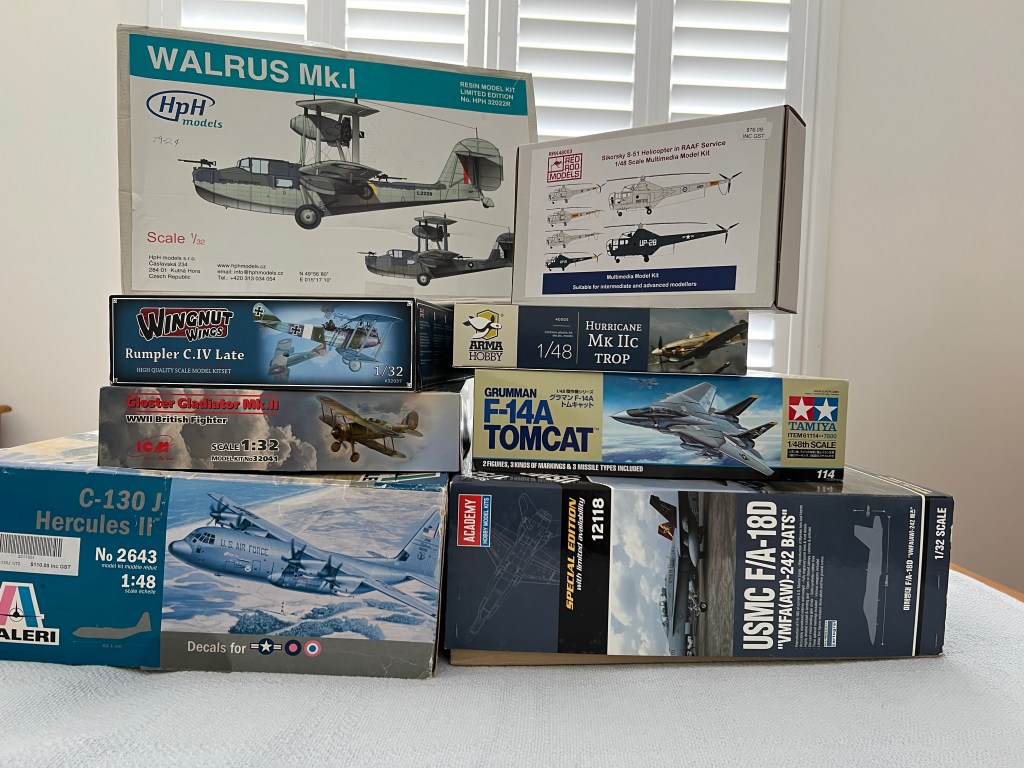
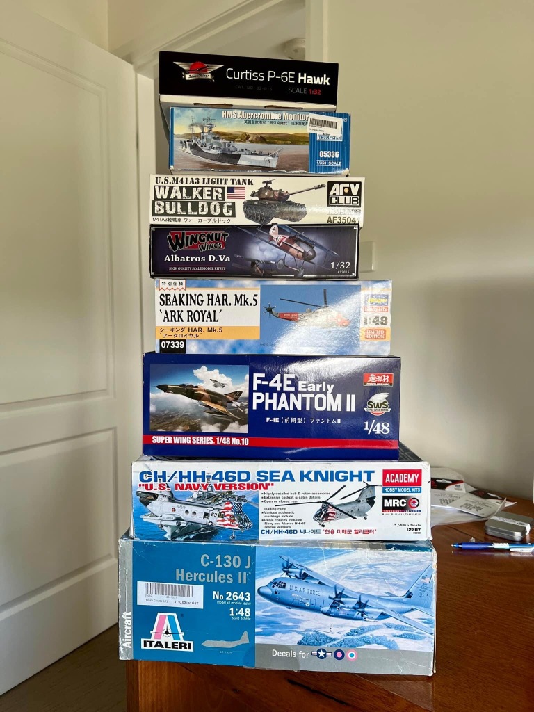
1/48 Avengers are the subject for this years “Thunderdome Build ” A small semi group build a few of my modelling mates conduct each year. Some finish, many don’t! ( Talking about YOU Gary ) The main contender for the kit choice being that we all have to have the chosen kit in our respective stashes.
My stash held two Avengers, one an original AM boxing, the other, an Italeri re-release. The intention was to build one and sell the other, however an inspection of both revealed one had been pre started and the other had many parts off the sprues.. That’s what you get for not checking boxes at swap and sellsI guess. Therefore it was decided to build both. One would be a Fleet Air Arm machine and the other, a USN machine. This would be my second AM build of the year, the first was the Dauntless, which I found an enjoyable build. This looked like it would be an equably enjoyable build..
Build Notes
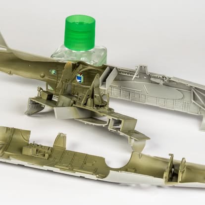
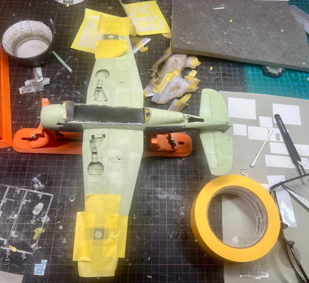
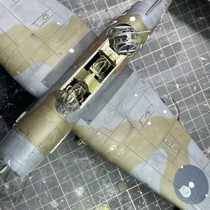
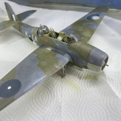
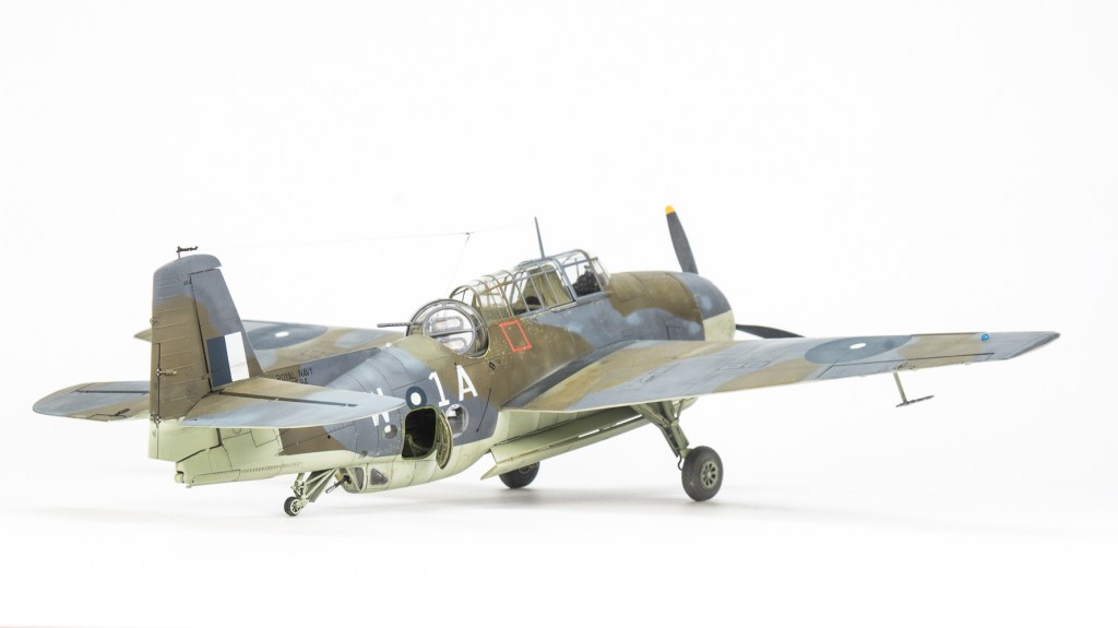
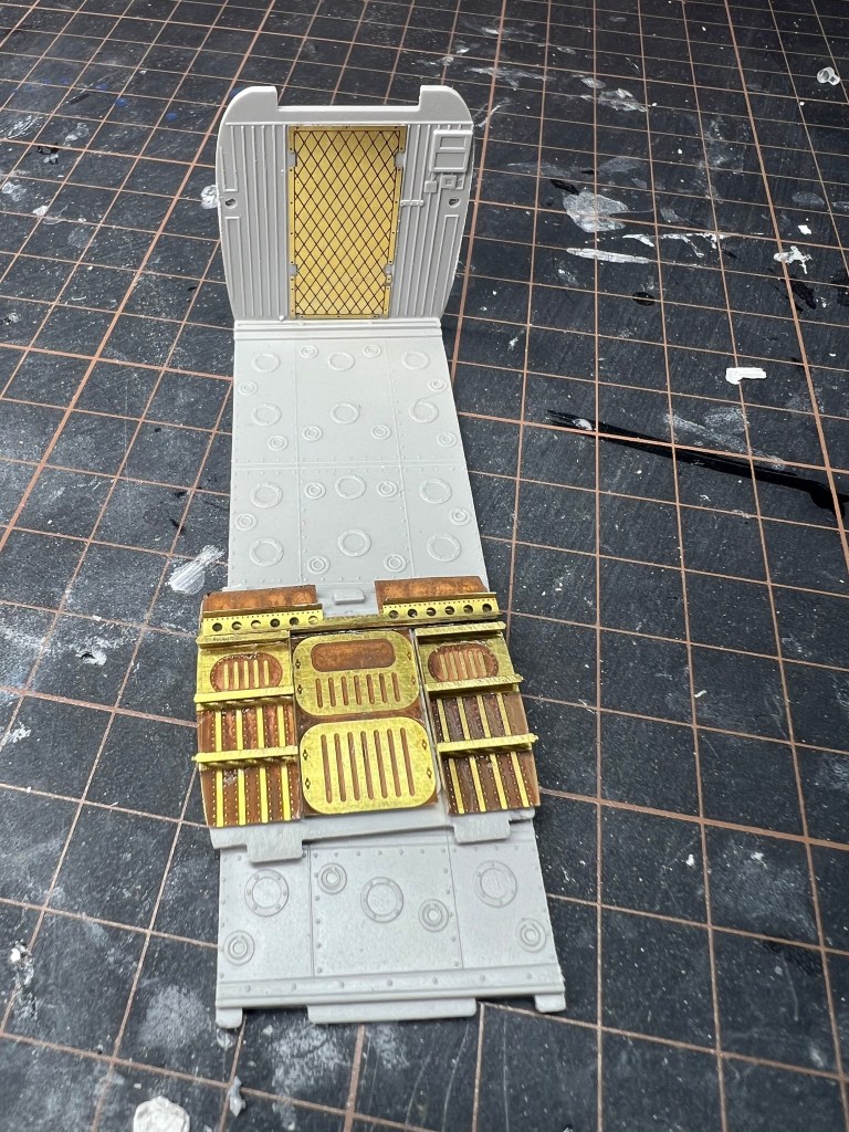
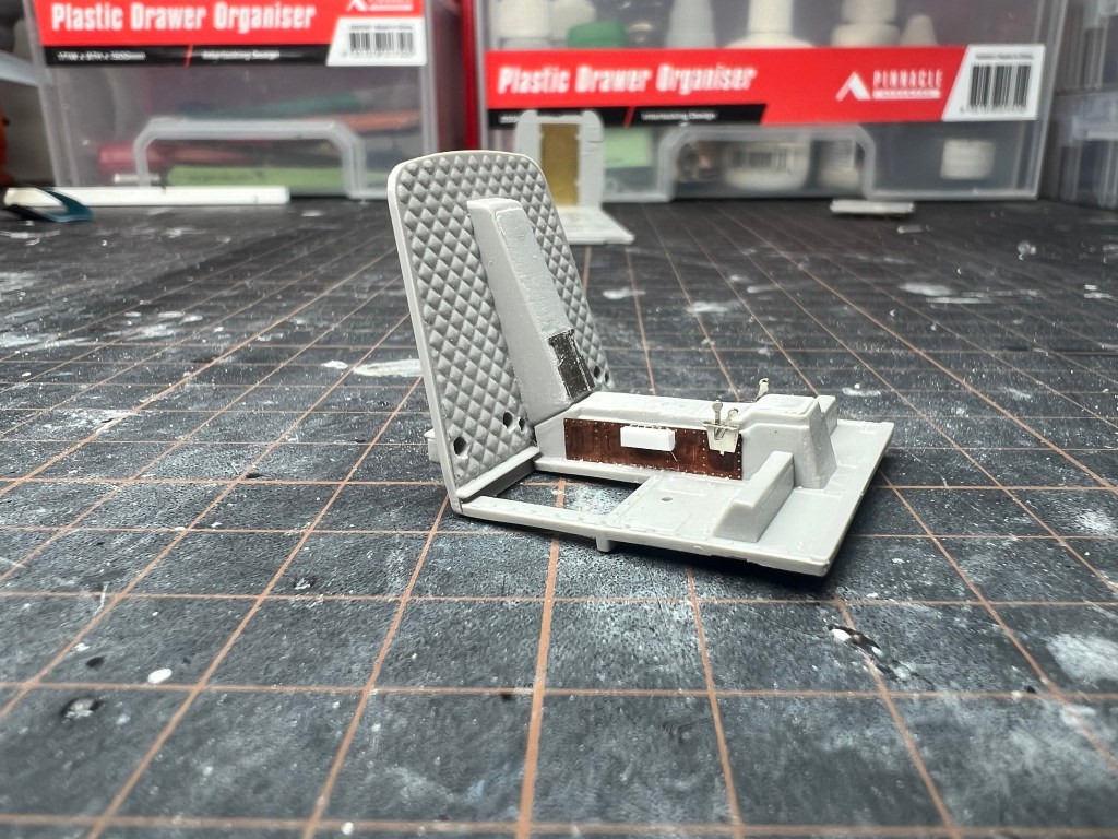
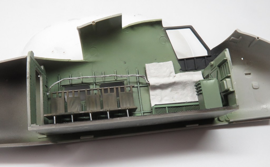
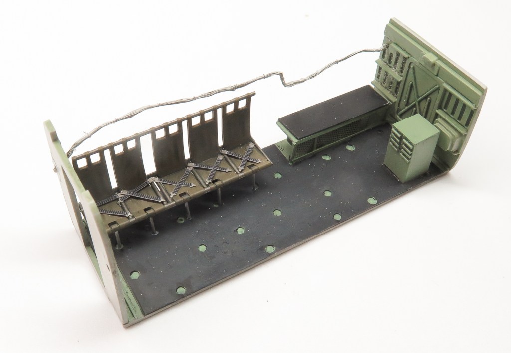
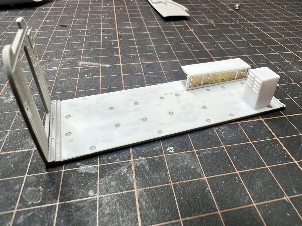
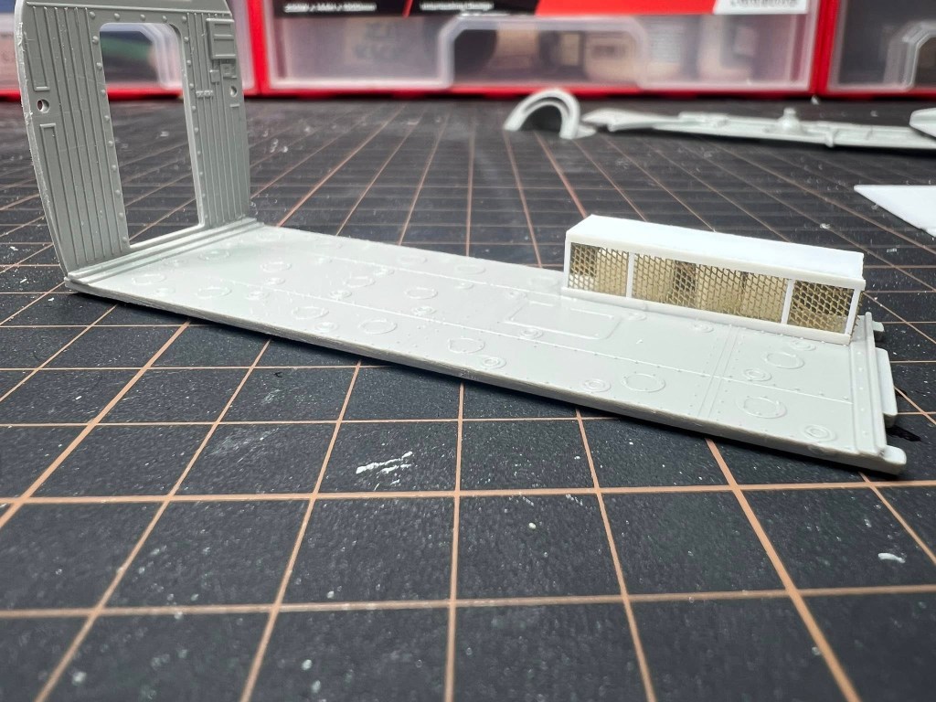
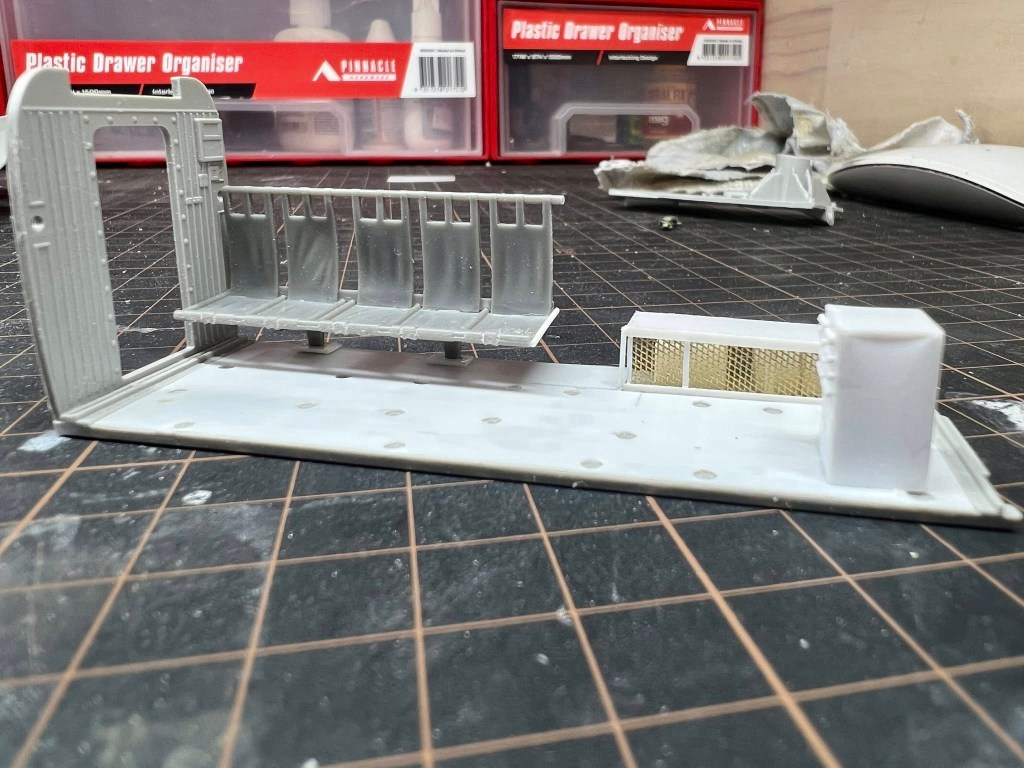
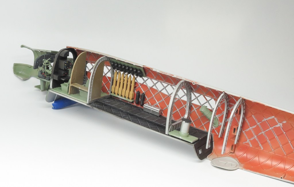
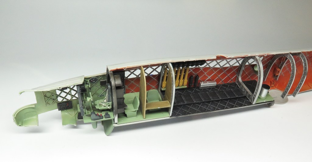
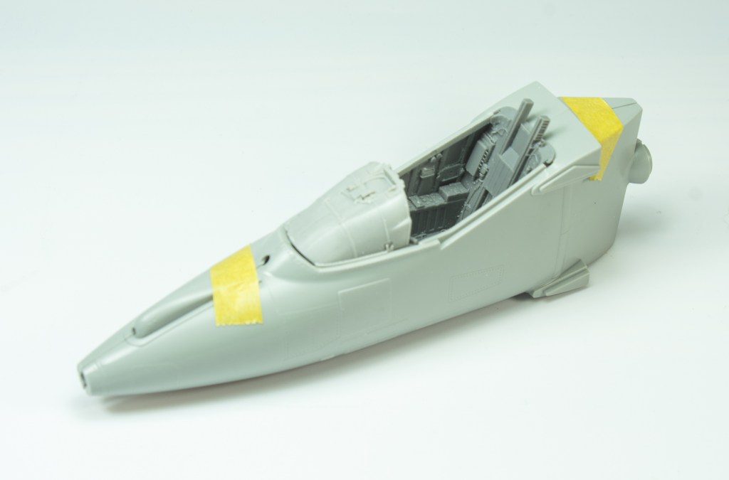
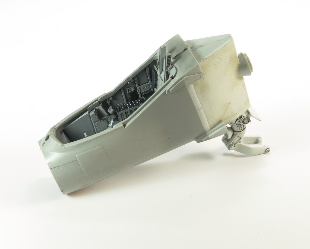
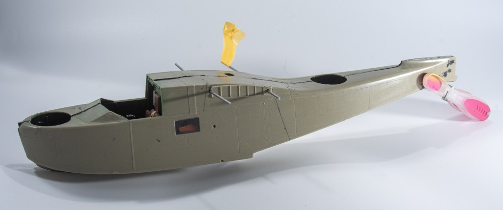
Being a FAA machine, the first thing to do was build the second cockpit position FAA machines had behind the pilot instead of the radio equipment the USN aircraft had, and the kit provides.
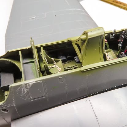
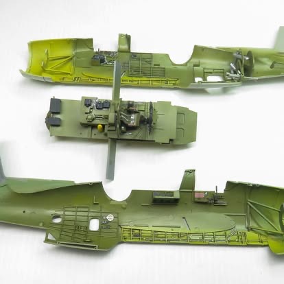
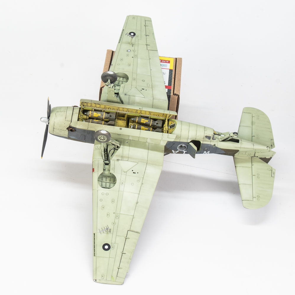
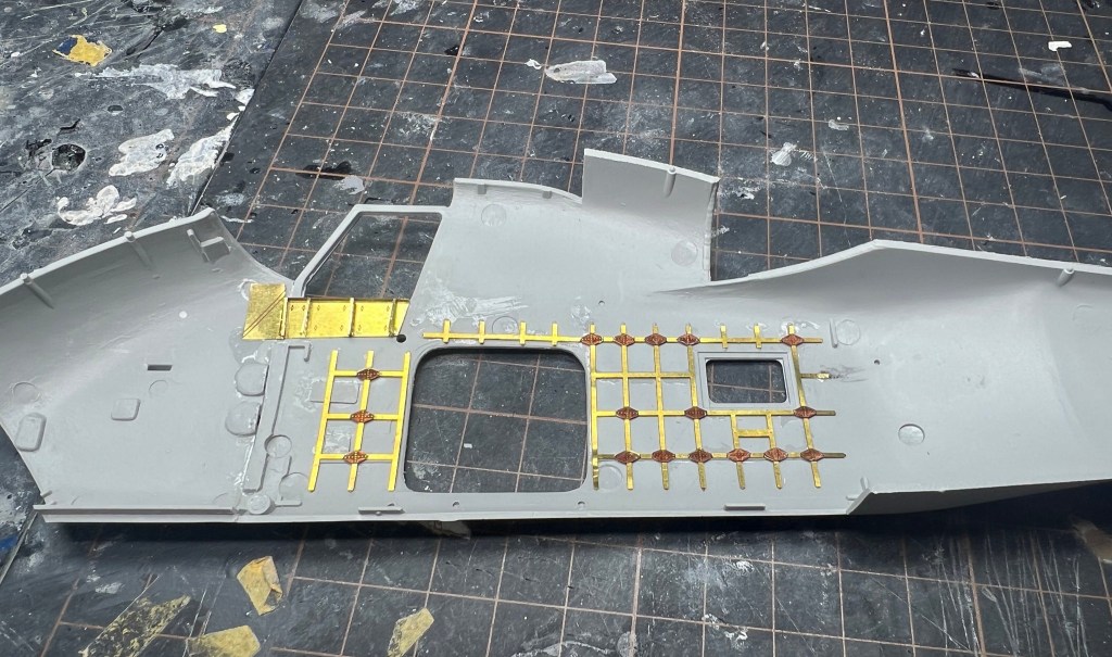
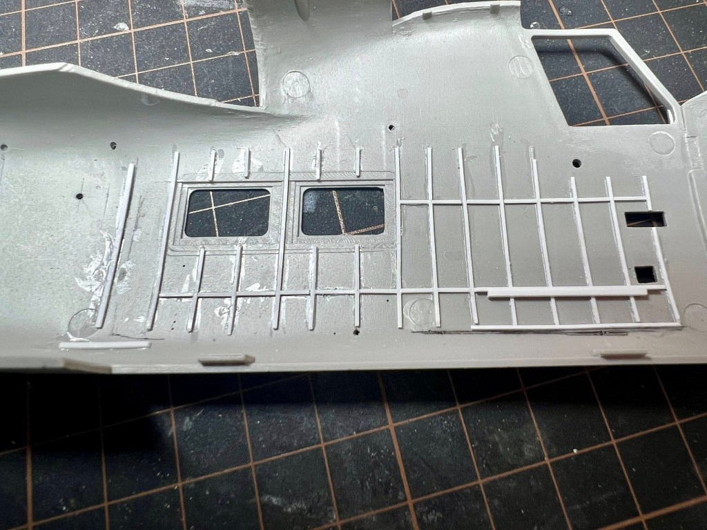
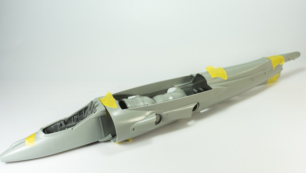
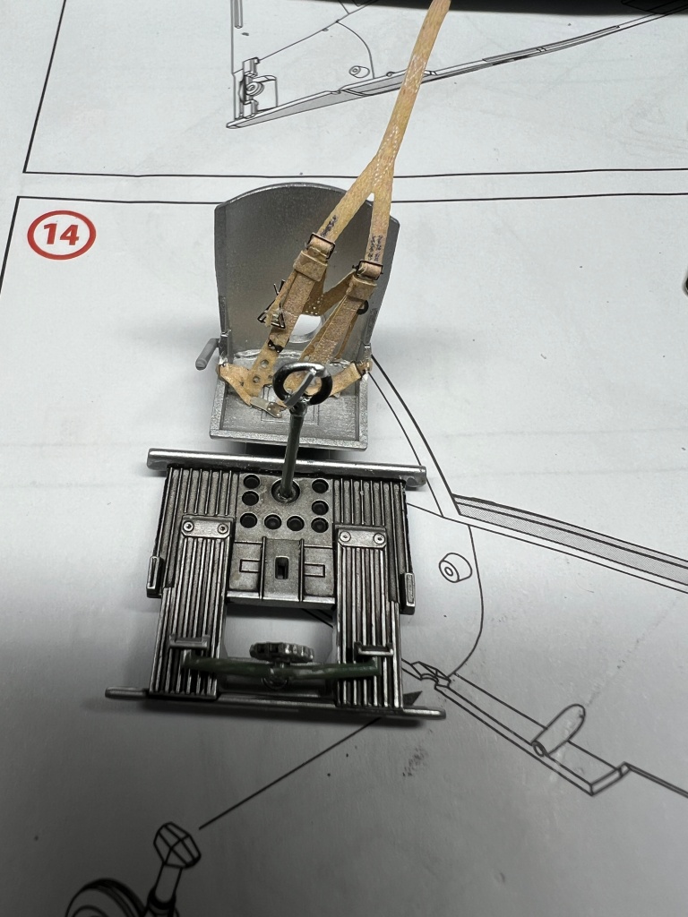
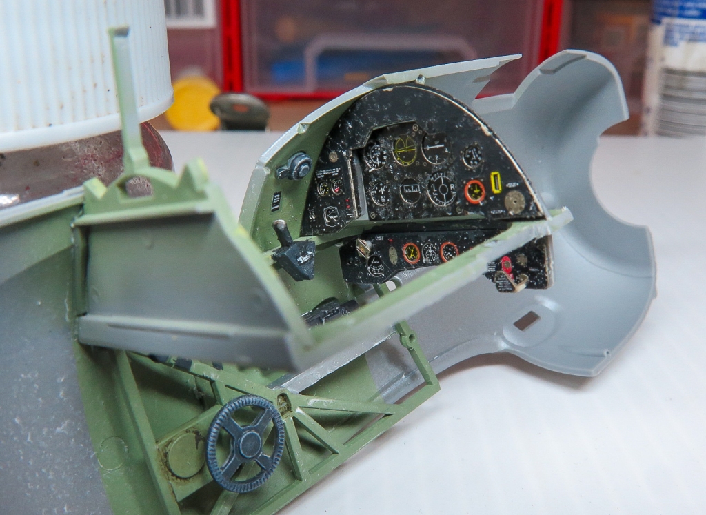
The moulded on detail on the floor was cut and chiselled off and a new floor using 15 thou plastic glued on. A spare Wildcat bucket seat was then added with a mounting frame made from brass wire. Sutton harness from Eduard was added to all seats. I didn’t go overboard on the detail figuring A Not much would be seen, and B. There are scant references available for how this area looked. As my chosen subject was an Eastern Motors built aircraft, the whole interior was painted Interior Green with SMS. The bomb bay and engine cowling were then painted Yellow Zinc Chromate with Tamiya XF4. Again I found the AM instructions poor in regard to where parts actually located, despite the written descriptions, particularly when it came to assembling the turret interior.
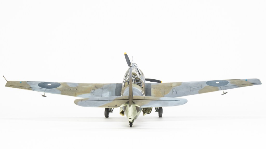
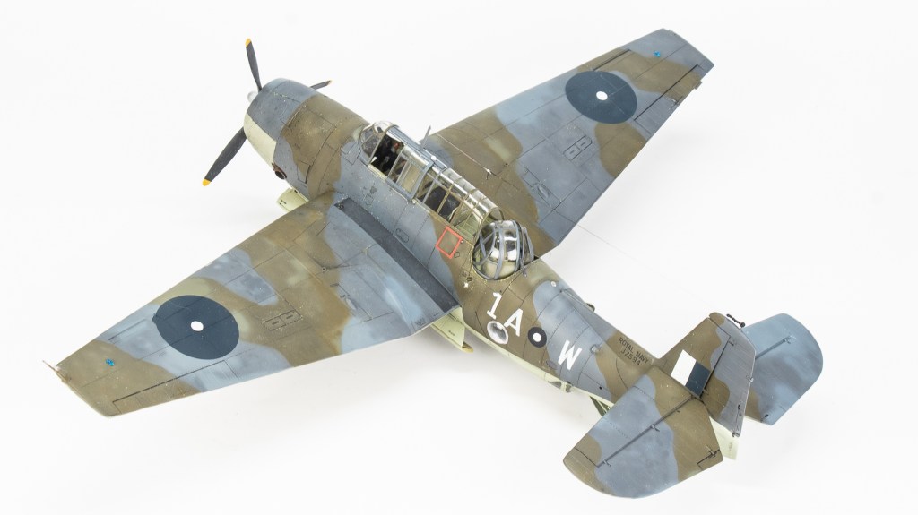
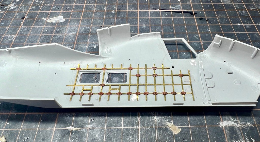
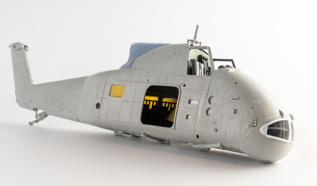
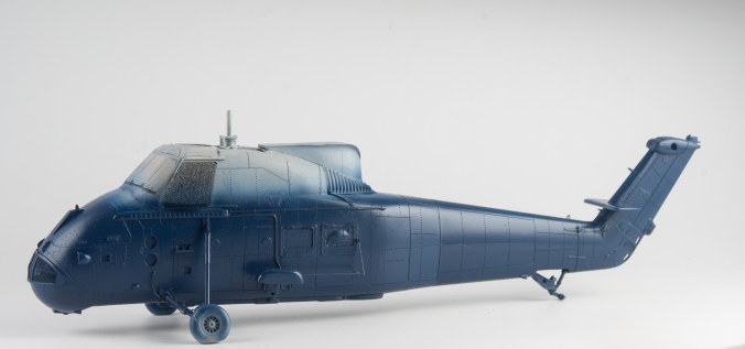
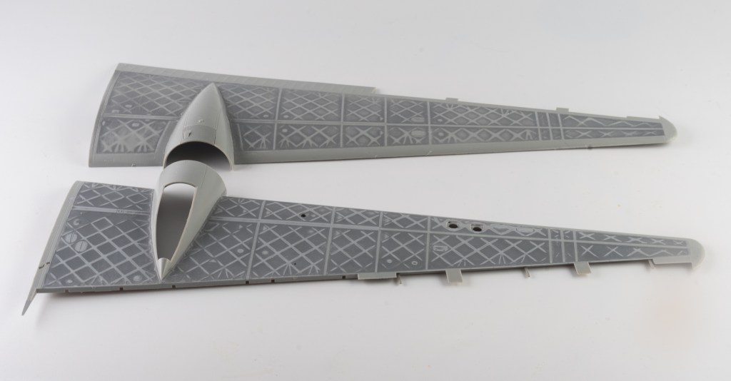
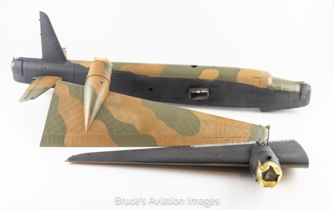
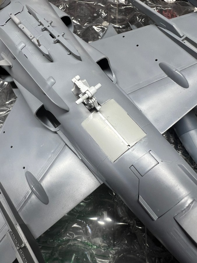
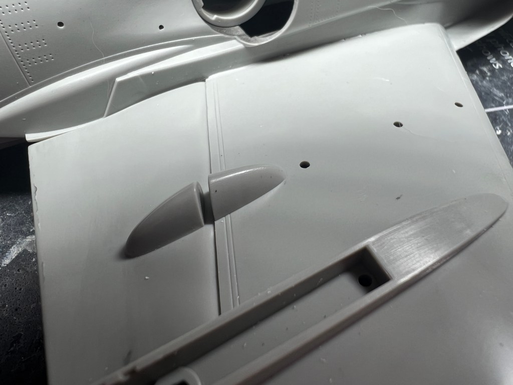
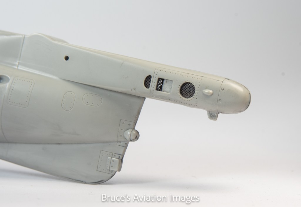
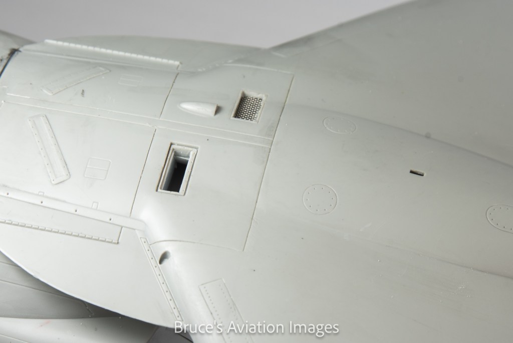
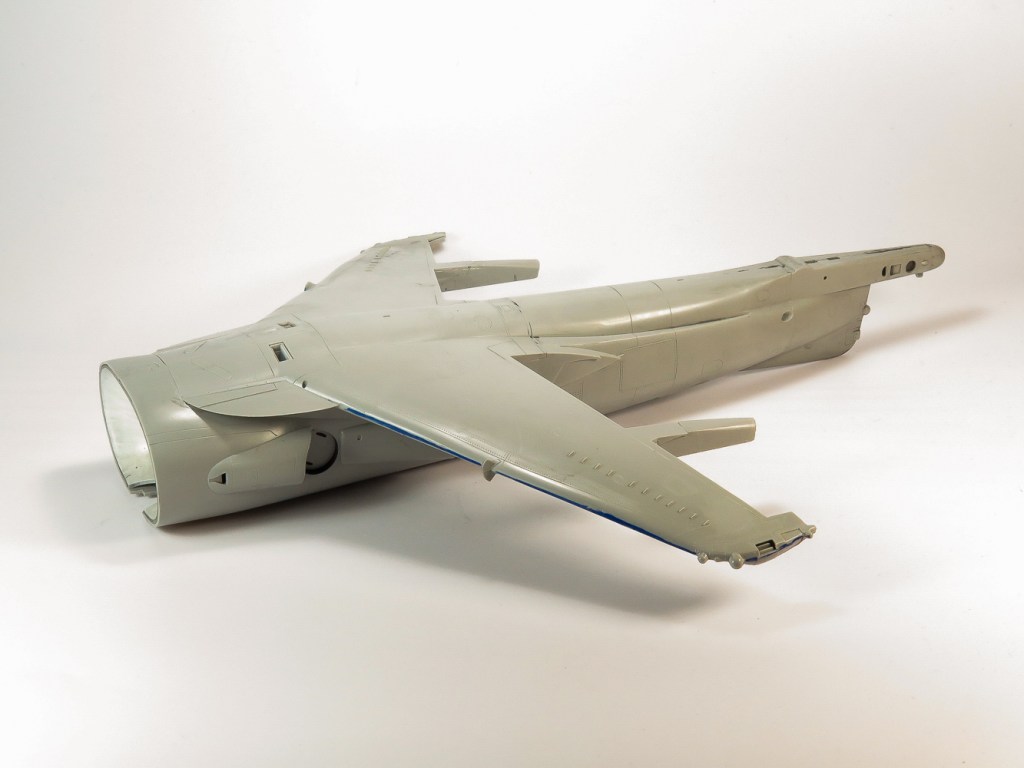
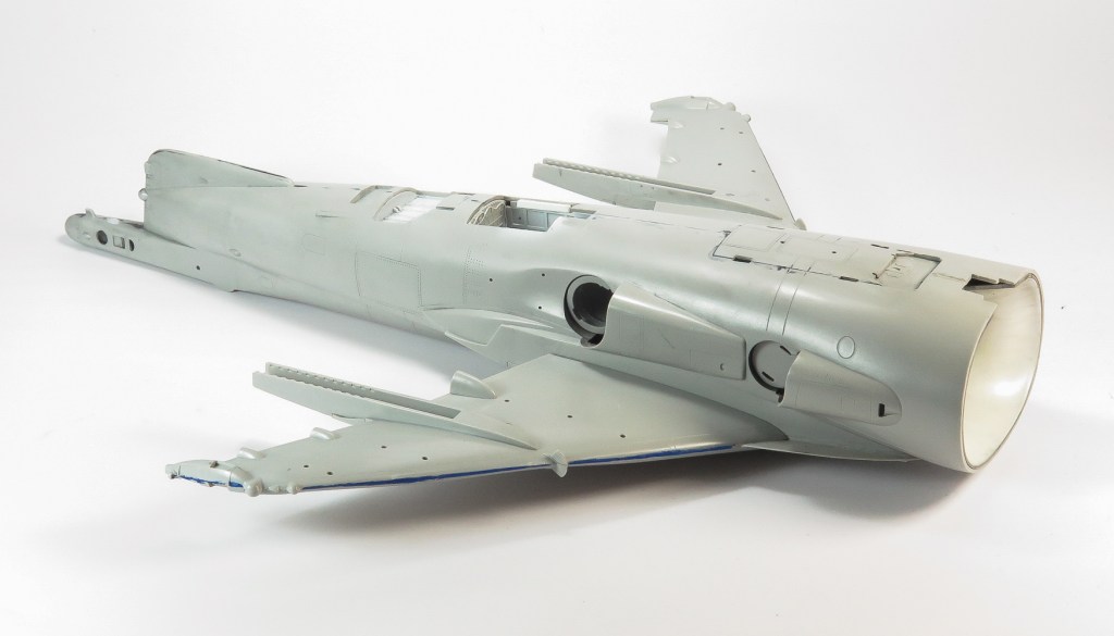
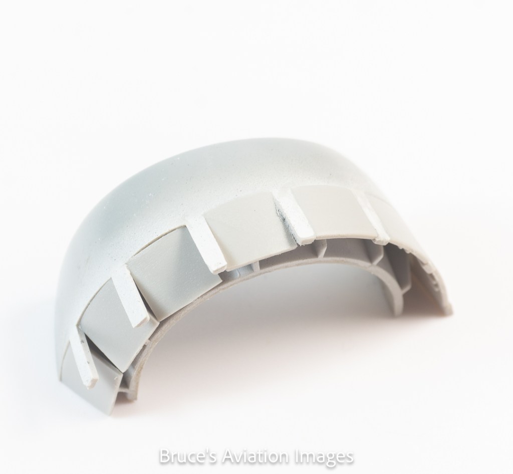
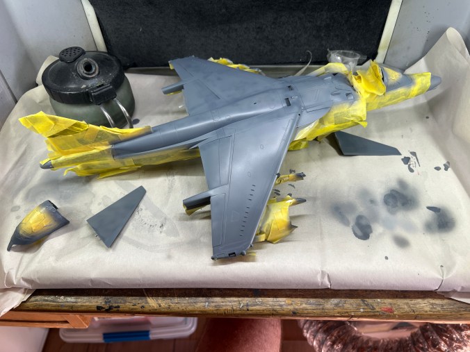
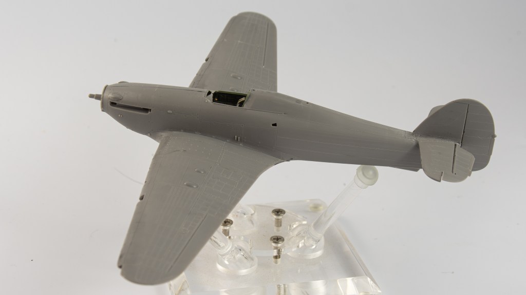
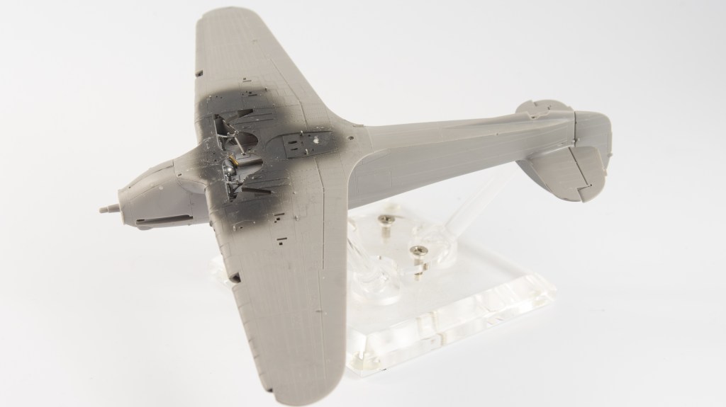
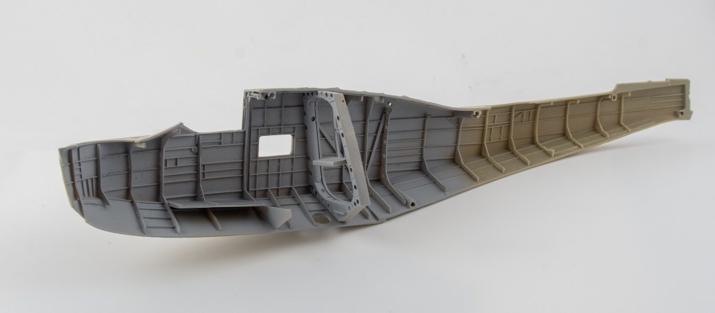
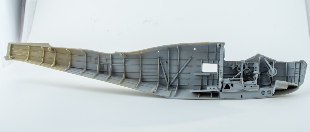
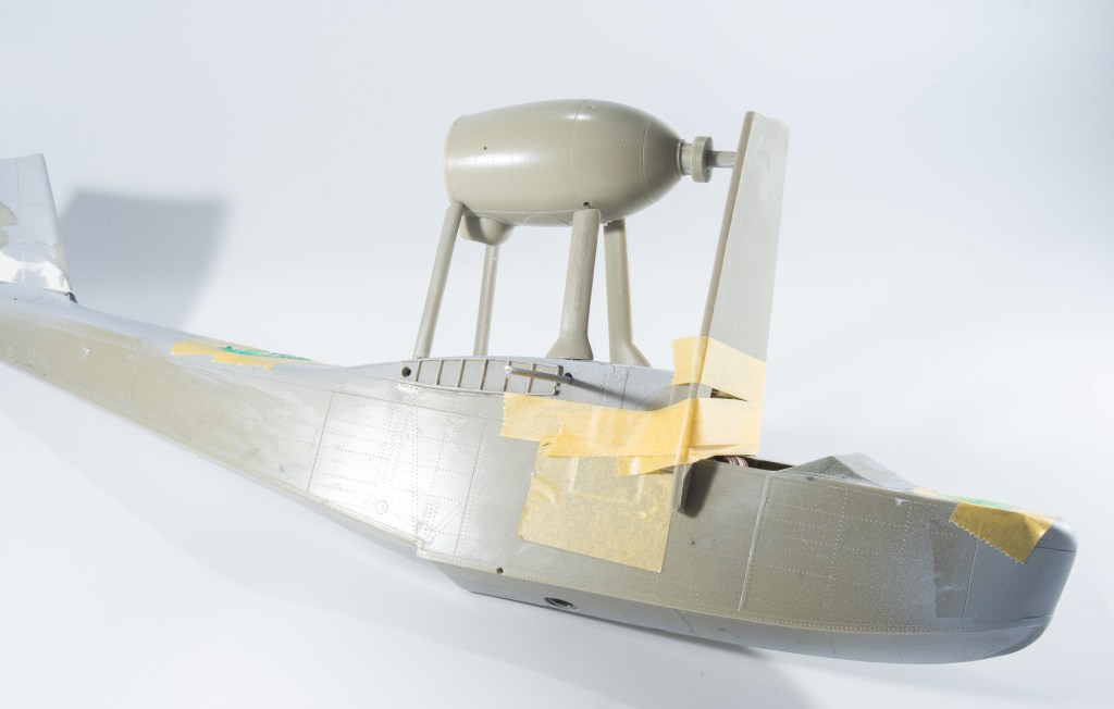
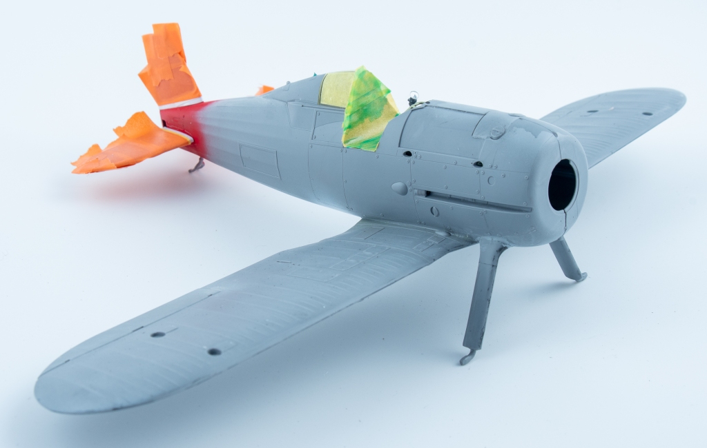
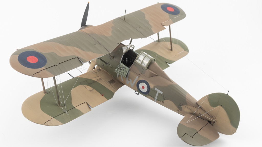
The airframe assembly proceeded without problem. I cut off the moulded on wingtip formation lights to allow me to add CMK blue lamps later on. A MV lens was also added to the leading edge landing light as out of the box, there is nothing, just a blank bulkhead. The fuselage small oval windows were also faired in to the surrounding fuselage using CA. This was sanded down and then polished to restore the window clarity. The kit windows had quite pronounced framing which I couldn’t see on any photos and look much better with the filling and sanding work. Being a FAA machine large bubble windows were fitted instead of the large rectangular windows. Accurate Miniatures, showing excellent foresight, include the bulged windows on the clear sprue in the kit. For a FAA machine, ensure that the raked back aerial post is used, the post on the real aircraft being hinged to allow the aircraft to be stowed in the lower height British Hangars. Aside from the above little refinements, the model was pretty much built as per the instructions, and went together with no great difficulties.
Painting and Finishing
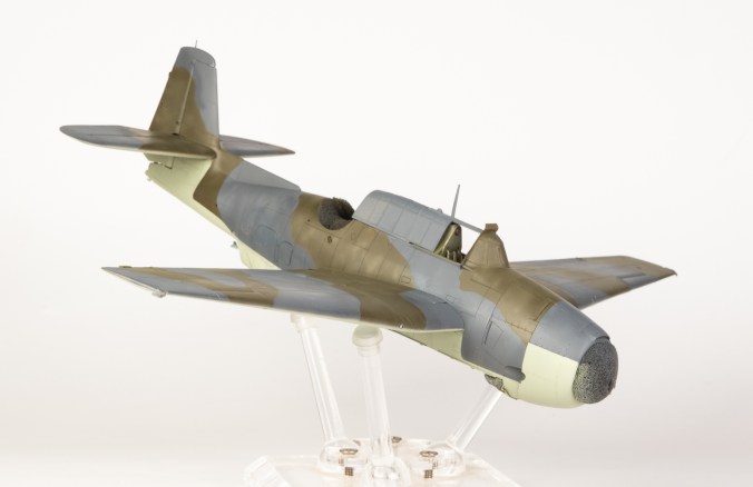
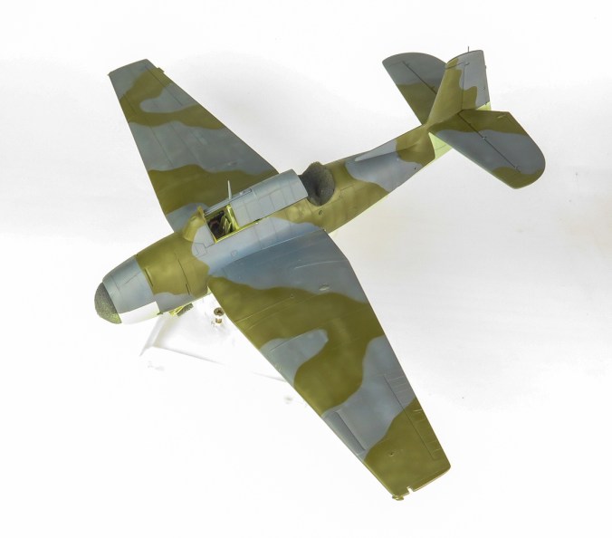
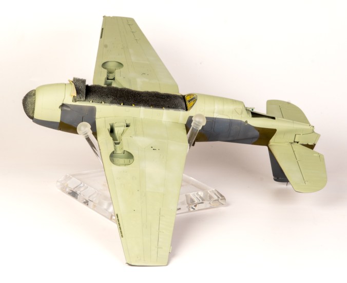
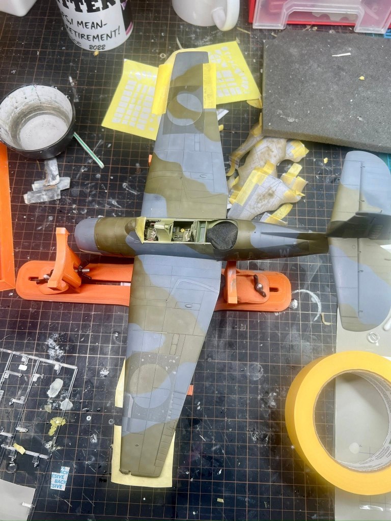
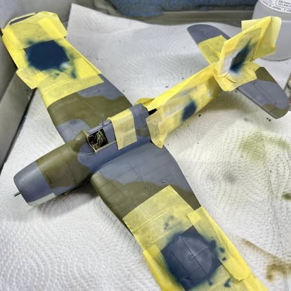
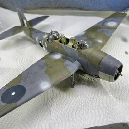
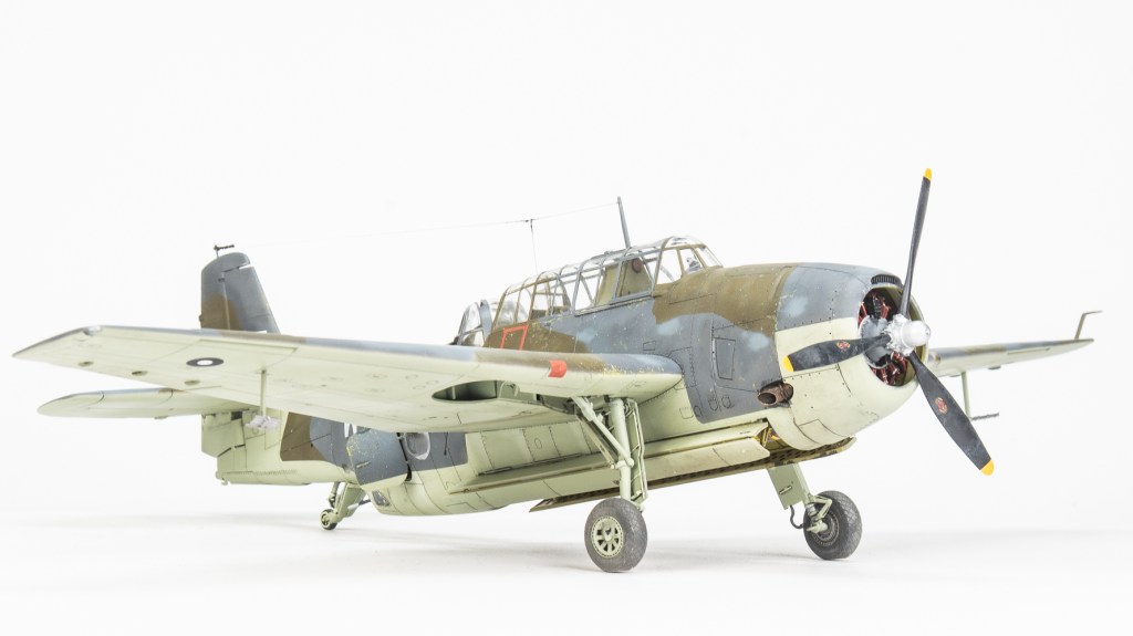
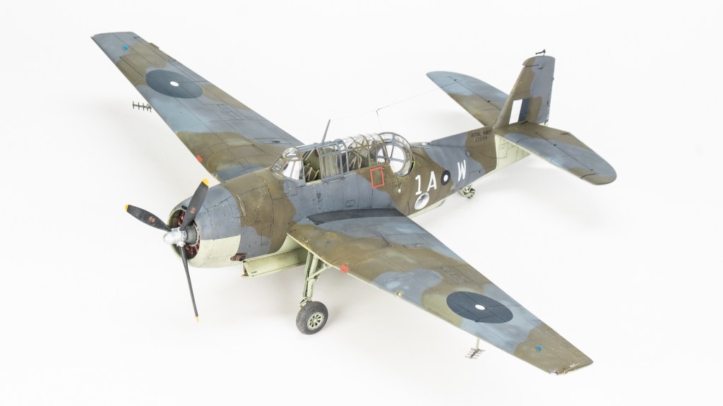
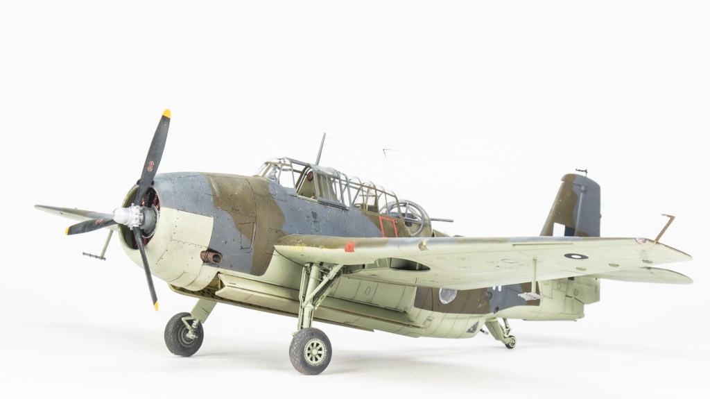
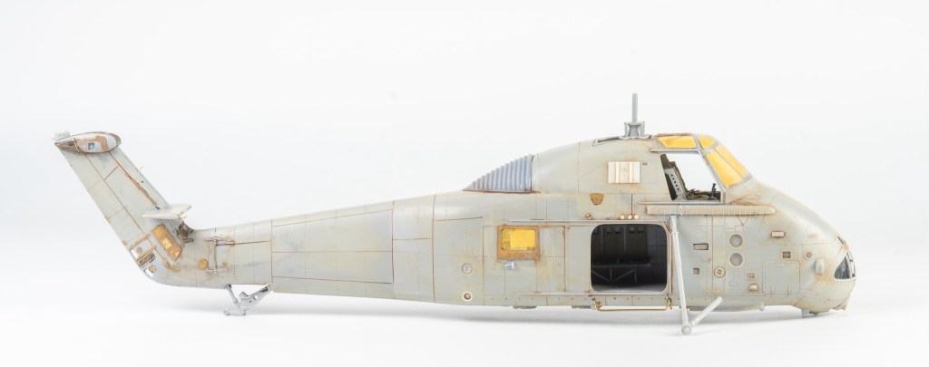
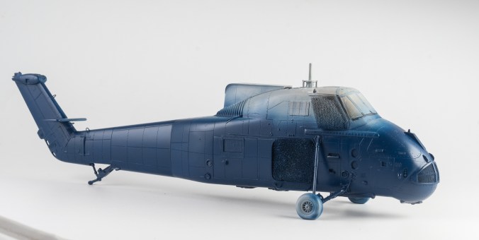
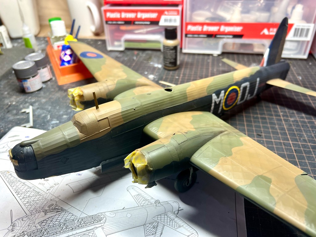
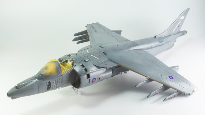
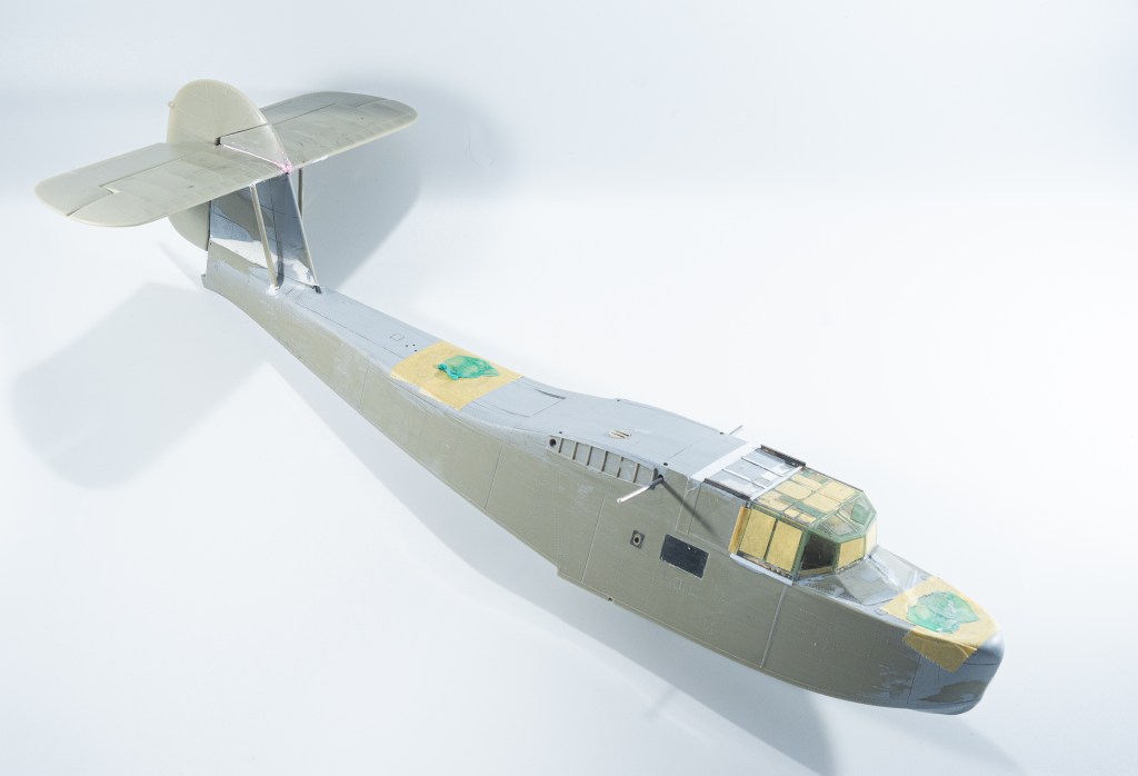
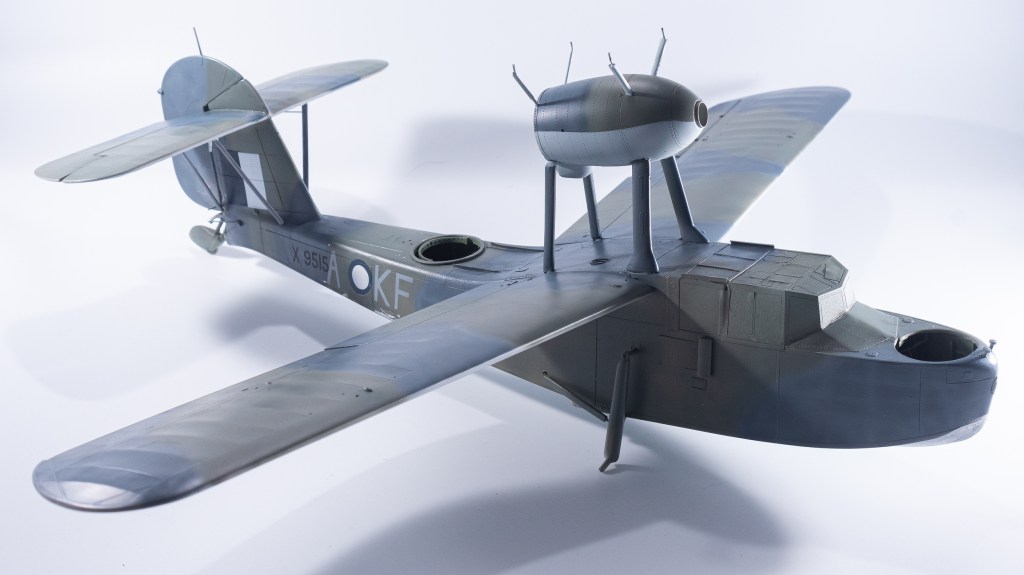
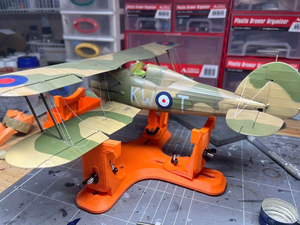
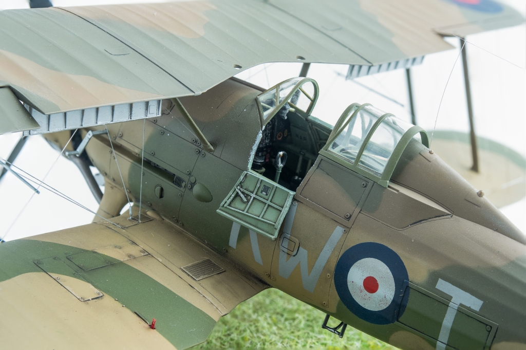
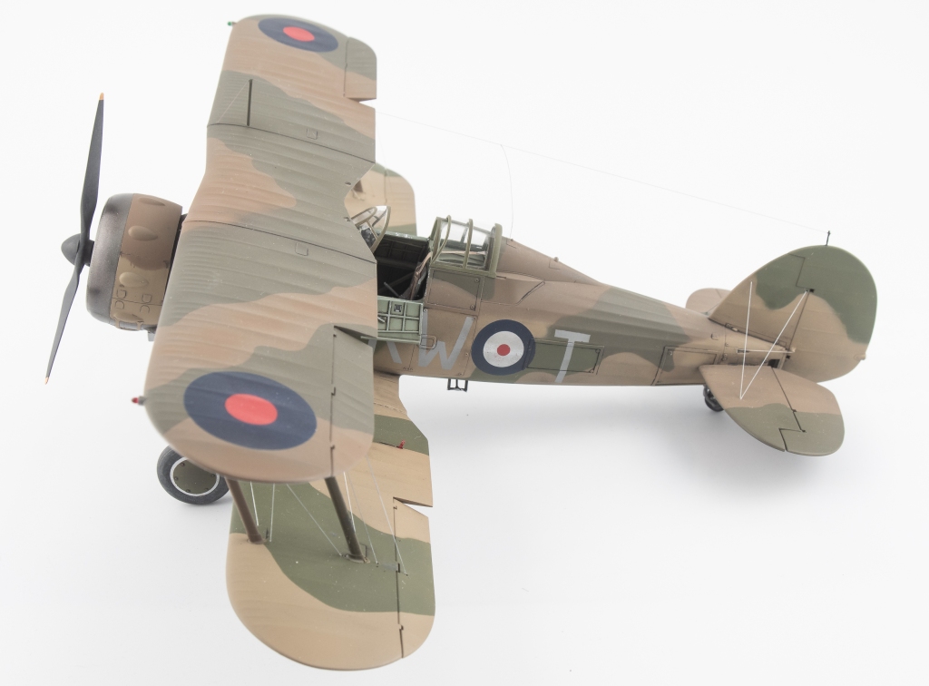
Being Eastern Motors built, my Avenger would be wearing ANA substitute colours. As far as the modeller is concerned, the main difference from the standard FAA colours is the use of ANA613 Olive Drab instead of Dark Slate Grey. MRP ANA Olive Drab was used for this The other colour used on the topside was ANA612 Sea Grey, which is pretty much Extra Dark Sea Grey. Tamiya XF24 standing in for this colour. All colours were lightened a touch with white. Undersides were Sky ANA 610. This shade was mixed from Tamiya colours using a recipe found on Britmodeller. After careful mixing, I was quite surprised the resultant colour wasn’t that far removed from RAF Sky, perhaps a touch greener. I was expecting a greyer colour as that’s what I have seen used on other models on line. For future FAA models of aircraft painted in ANA colours, I’ll just use a RAF sky straight from the jar.
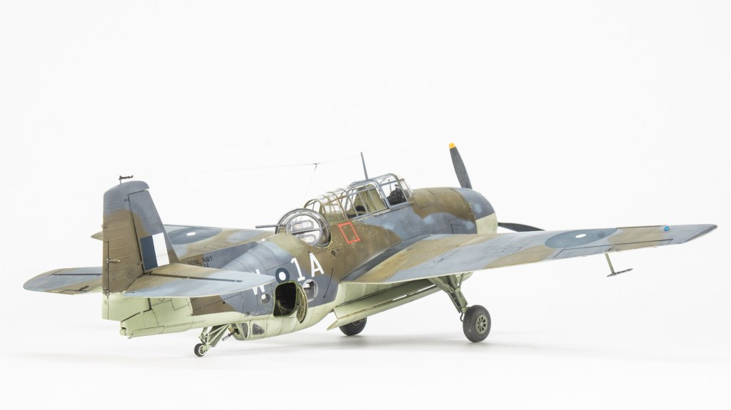
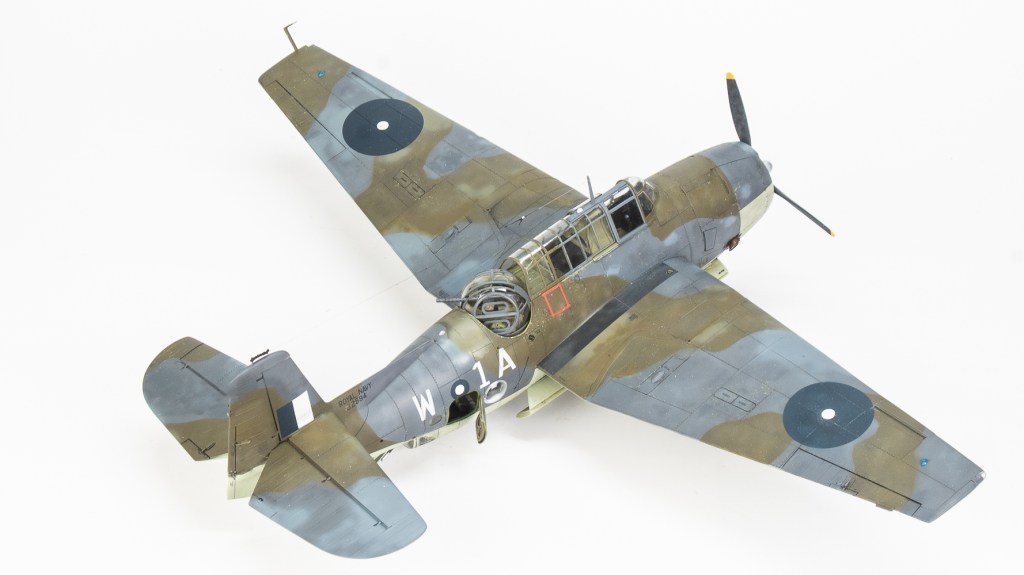
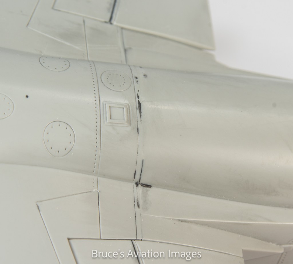
All these colours were gone over with lightened and darkened mixes of each colour to make the aircraft look weatherbeaten and patched up in appearance. Reading about the raids conducted by these aircraft, very few escaped unscathed, in fact I would not be surprised if this actual aircraft was lost. All this battle damage repair, I’m sure would have lead to a multi hued surface, and then there is fading and being exposed to the elements on flight decks to contend with.
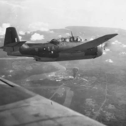
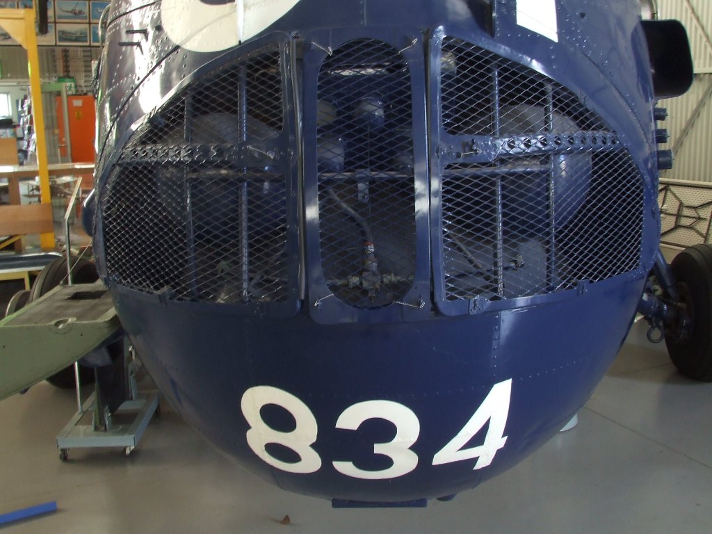
This website https://www.destinationsjourney.com/historical-military-photographs/grumman-avenger-in-british-service/ has some excellent photos of British Avengers.
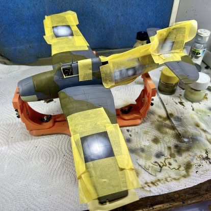
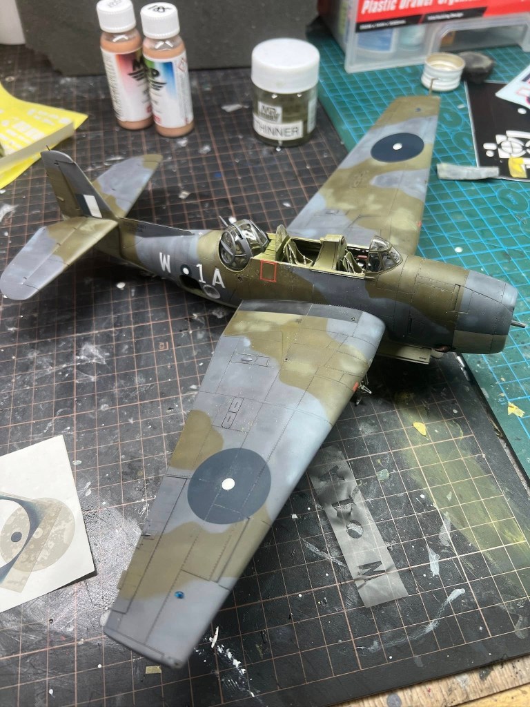
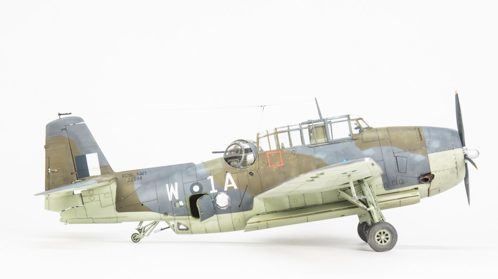
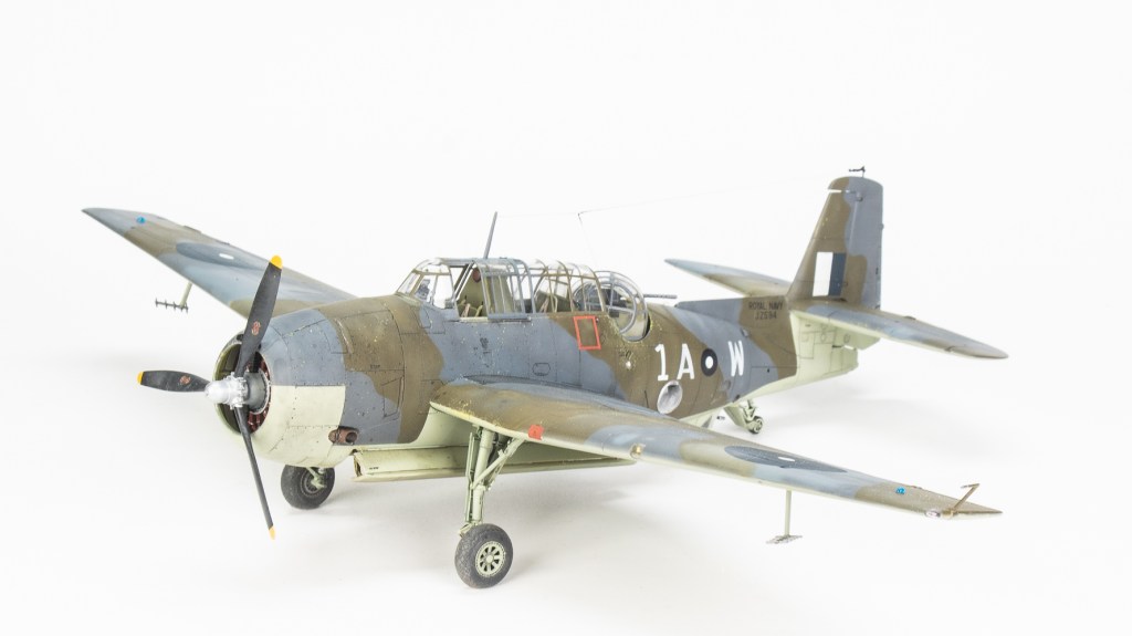
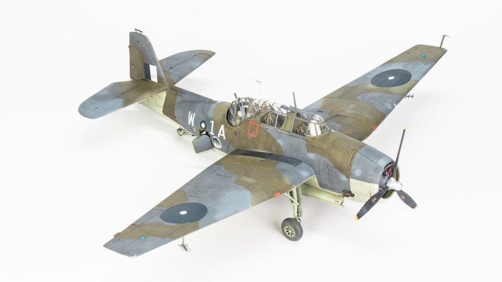
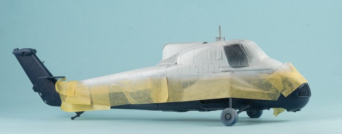
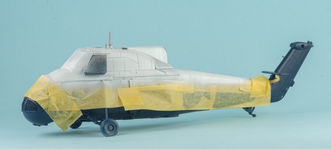
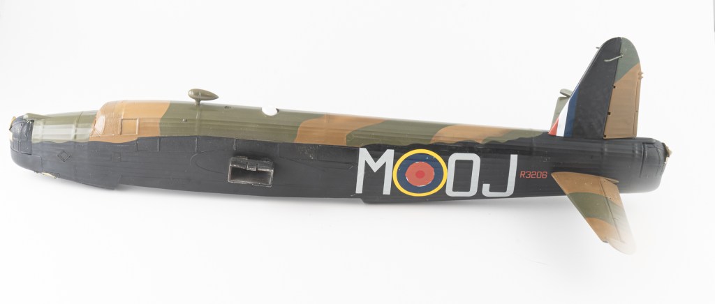
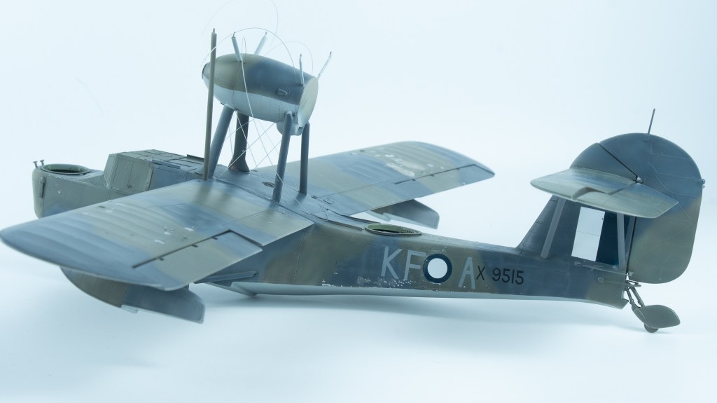
Markings for the aircraft I wanted to do were not available as part of any decal sheet, so using an Aeromaster sheet to get the dimensions of the roundels, masks were cut on my Silhouette. The codes were sized against the photo and also cut, although these should probably have been about 2 mm less in height. Serial numbers from the Aeromaster sheet were rearranged to get the number. These and the maintenance stencils were the only decals used on the model.
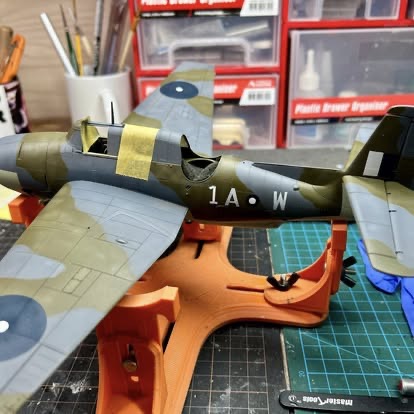
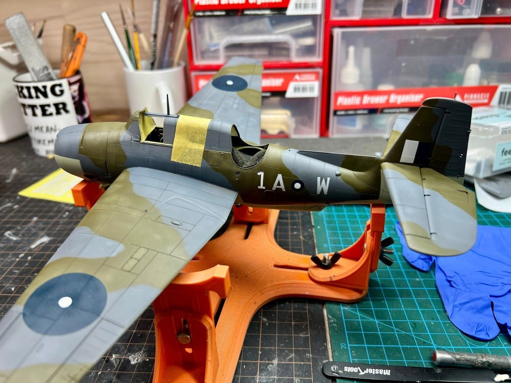
I have to admit to feeling quite pleased with the results, especially as the markings had been completed in one go without all the touch-ups normally needed on one of my models.
Alas, I spoke too soon
In hindsight, YES, shaking a paint pen with the lid off AND over the model was reckless! This then led to repeated rounds of sanding priming and touch-ups to get back to where I had been a day ago. I would get a lot more models finished if I didn’t continuously have to do things twice.
If there was a silver lining to this, it was that I could introduce even more colour variations to the model. These aircraft suffered greatly through battle damage and exposure to the harsh sun and salt air, so would have started to look fairly tatty after not too long
Finishing
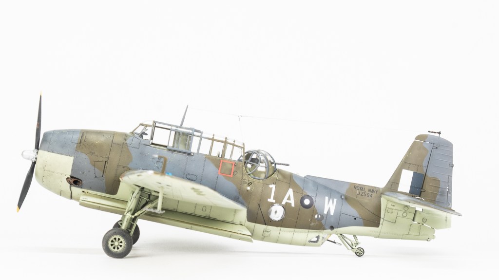
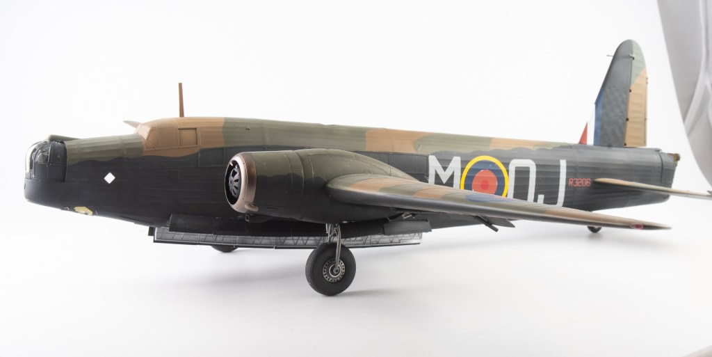
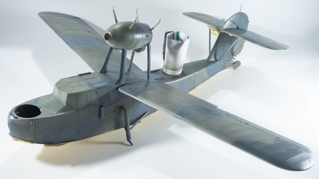
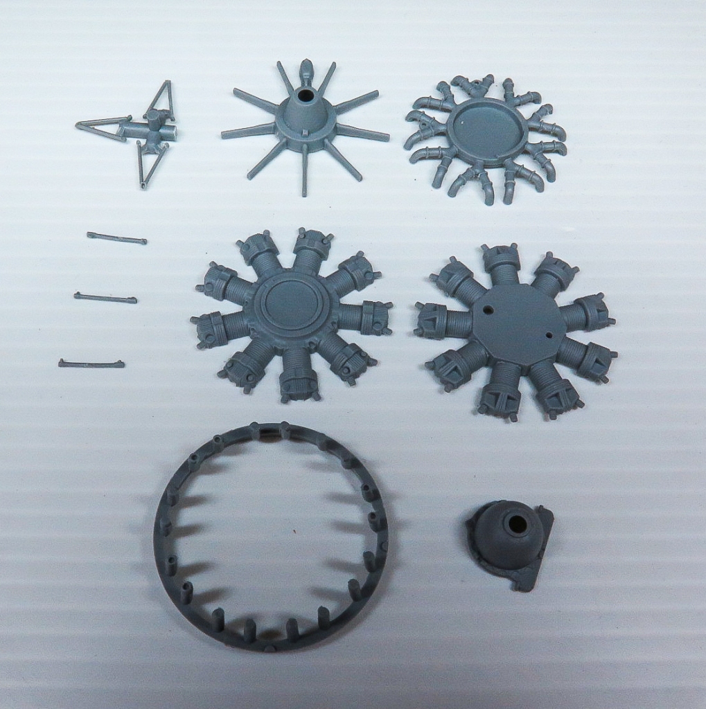
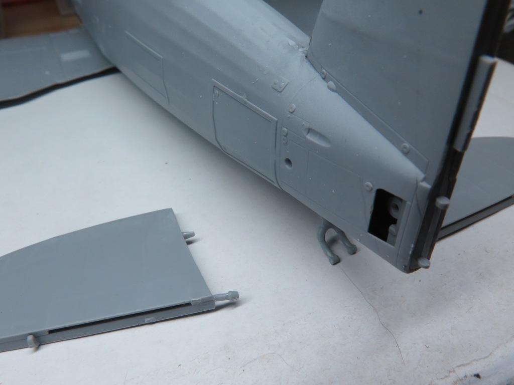
Modellers World grey brown wash was flowed into all the panel lines with the excess rubbed off. The transparencies were then added including that dreaded turret everyone seems to complain about fitting. In the end, it actually wasn’t that difficult. My next Avenger post will contain step by step photos on the procedure. The landing gear was added, fitting very securely into its large location slots. In fact, the engineering all through this kit was well thought out and resulted in a solid airframe. Quickboost exhaust pipes replaced the rather thick kit parts. They were base coated dark earth and then stippled with rust and light grey tones. You will need to remove the small location tab in the fuselage exhaust cutouts before glueing the resin items in place. The transparencies were then unmasked and an aerial line added from EZline (Yes, I know I said I would not use this stuff again )
Final Thoughts
It struck me halfway through this build in my 56 years of modelling this was the first time I had built an Avenger!
The kit itself went together reasonably quickly and painlessly and was an enjoyable build. On the shelf it further reinforces my thought EVERYTHING looks good in FAA colours!
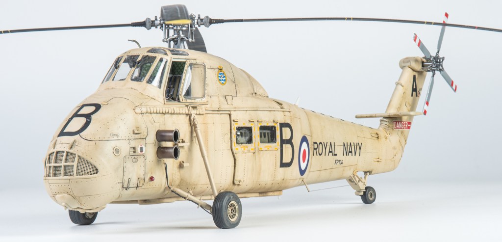
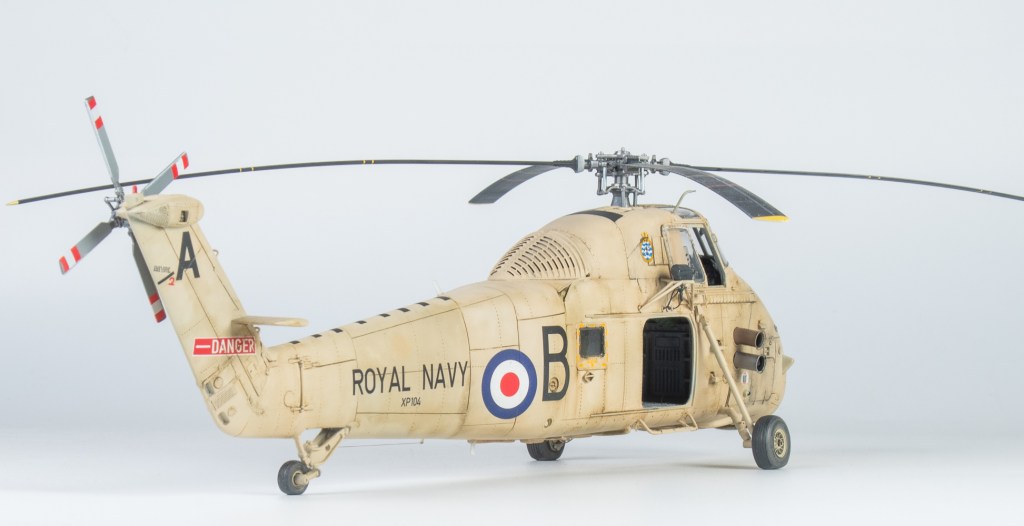
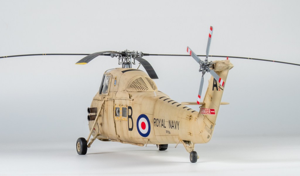
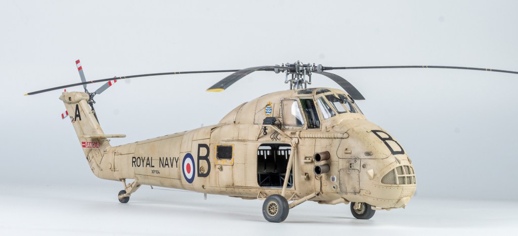
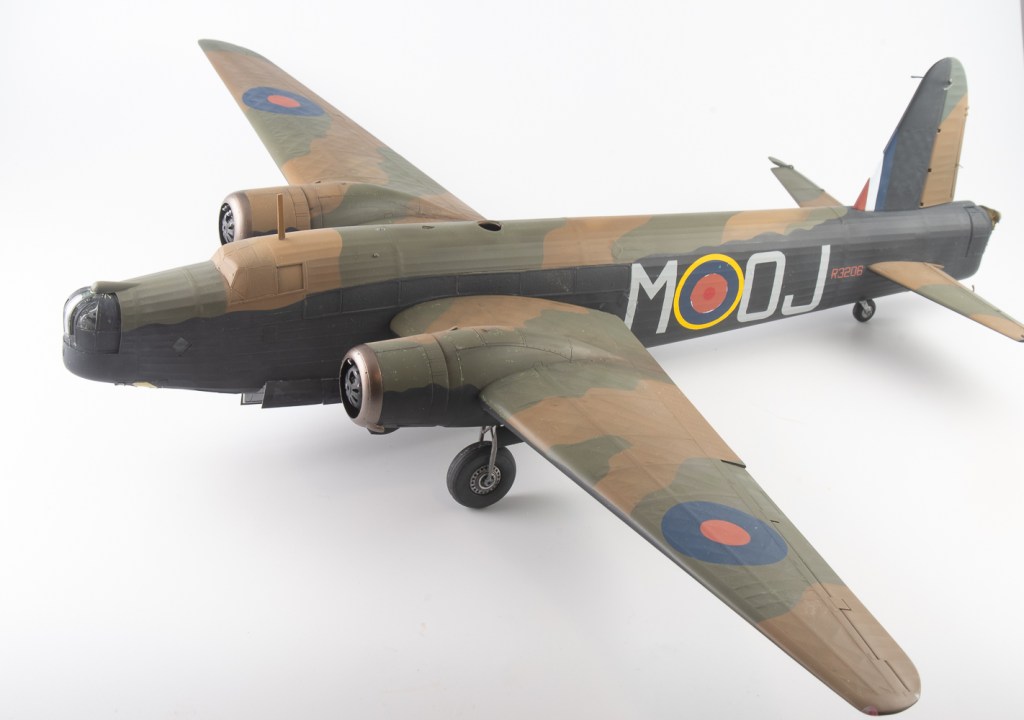
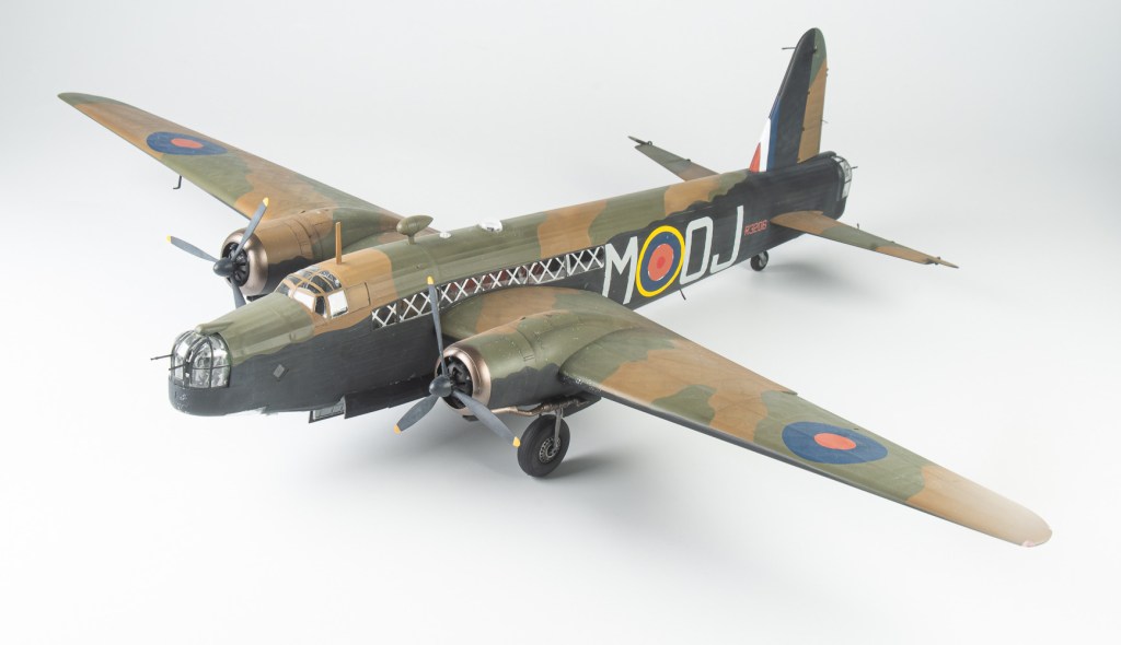
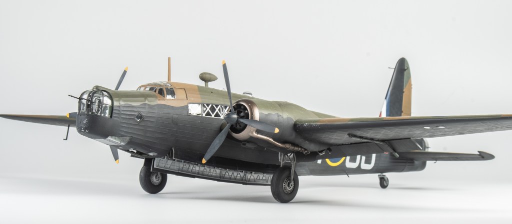
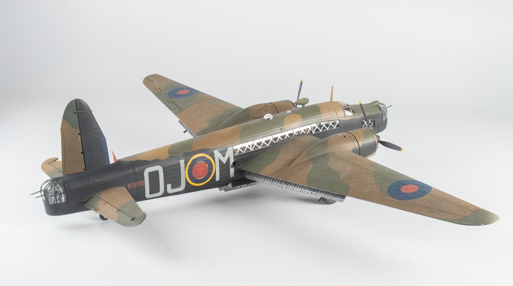
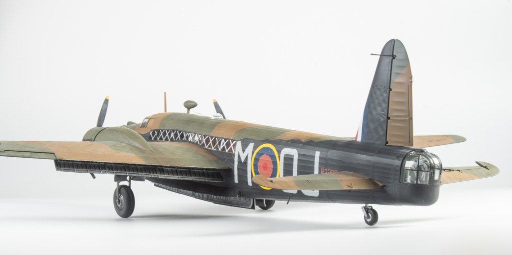
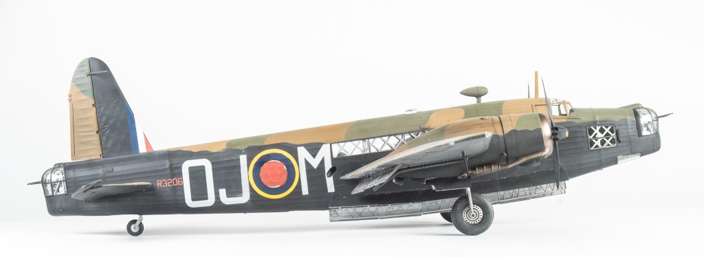
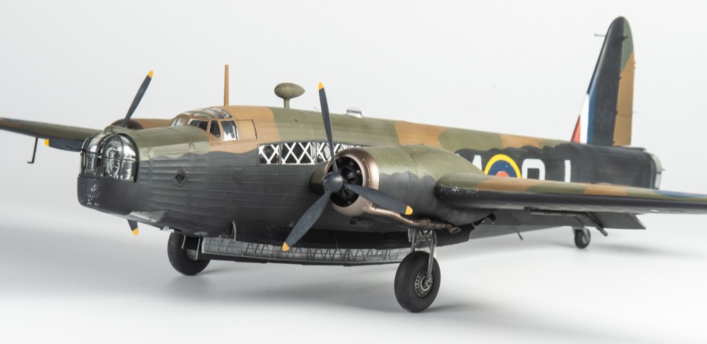
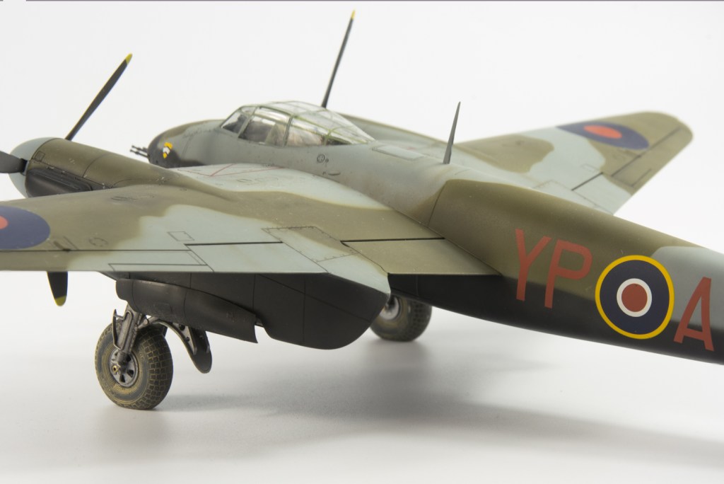
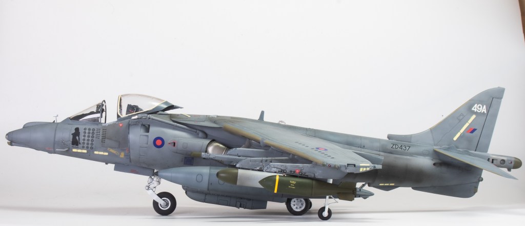
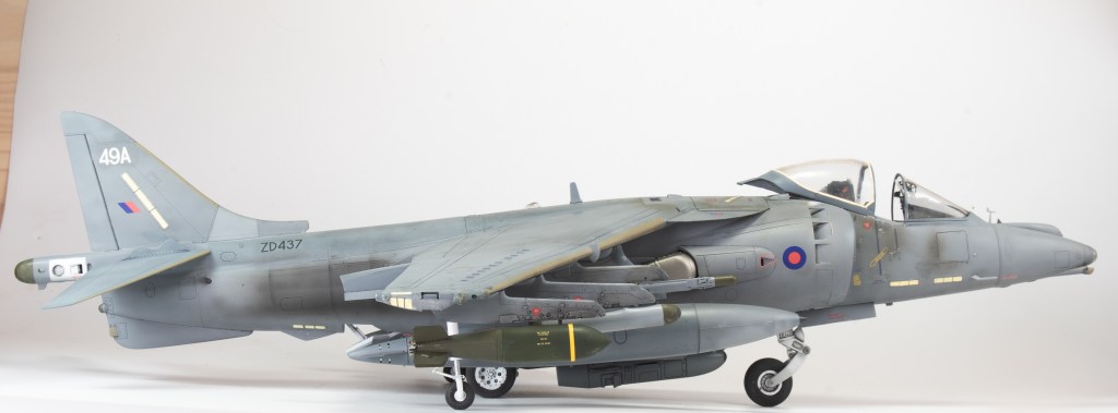
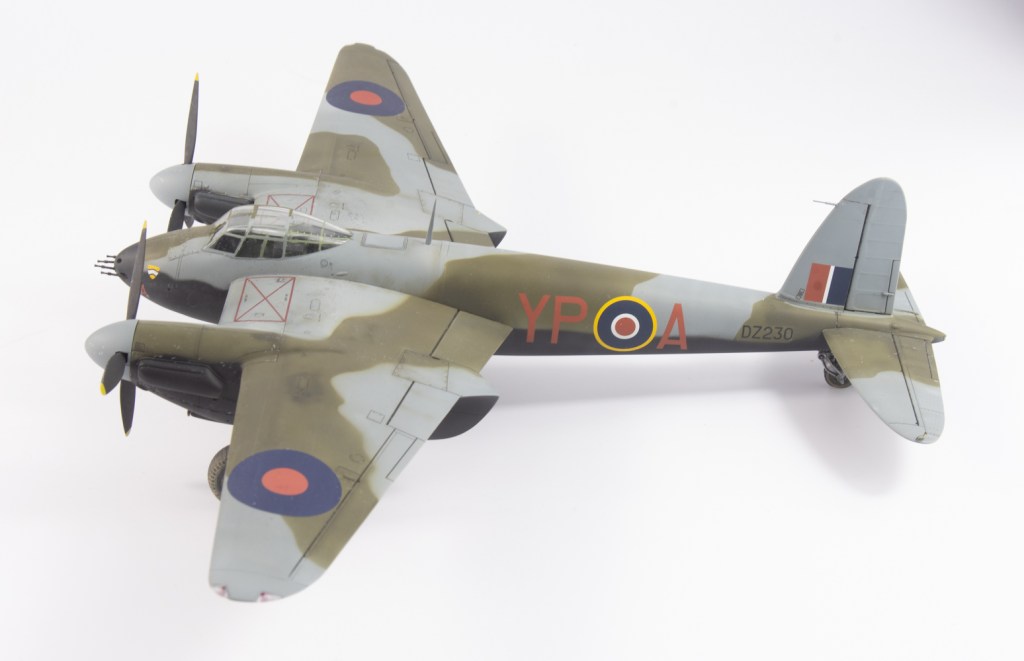
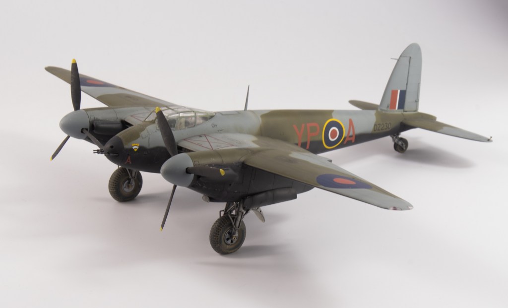
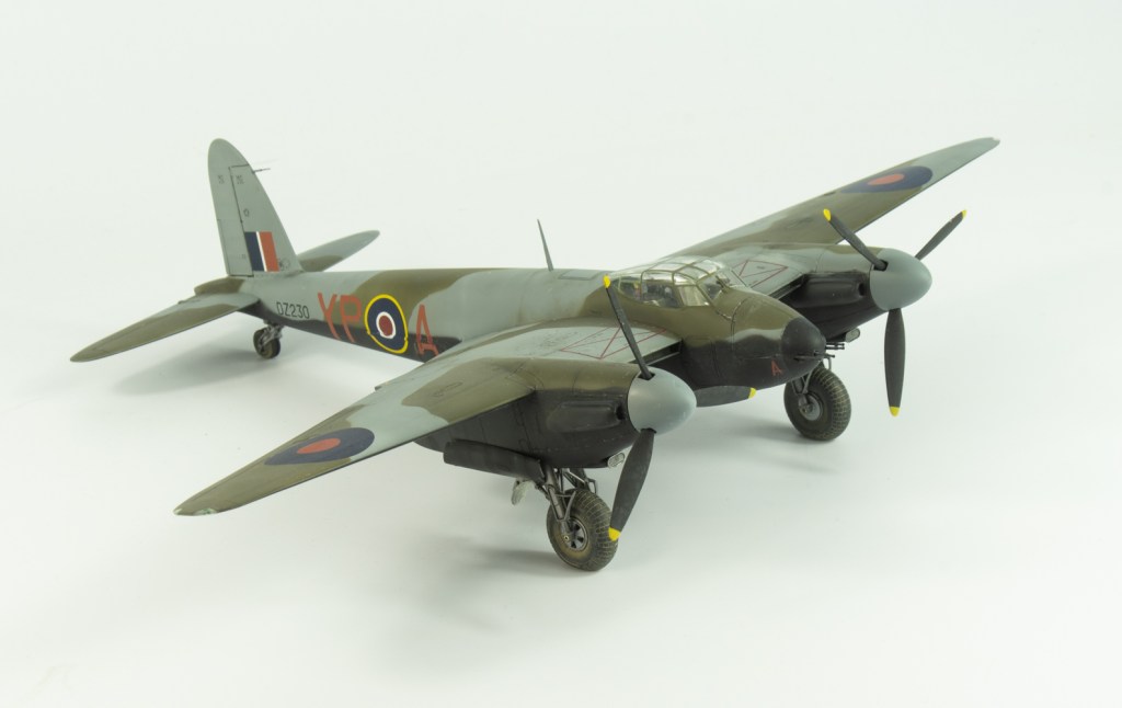
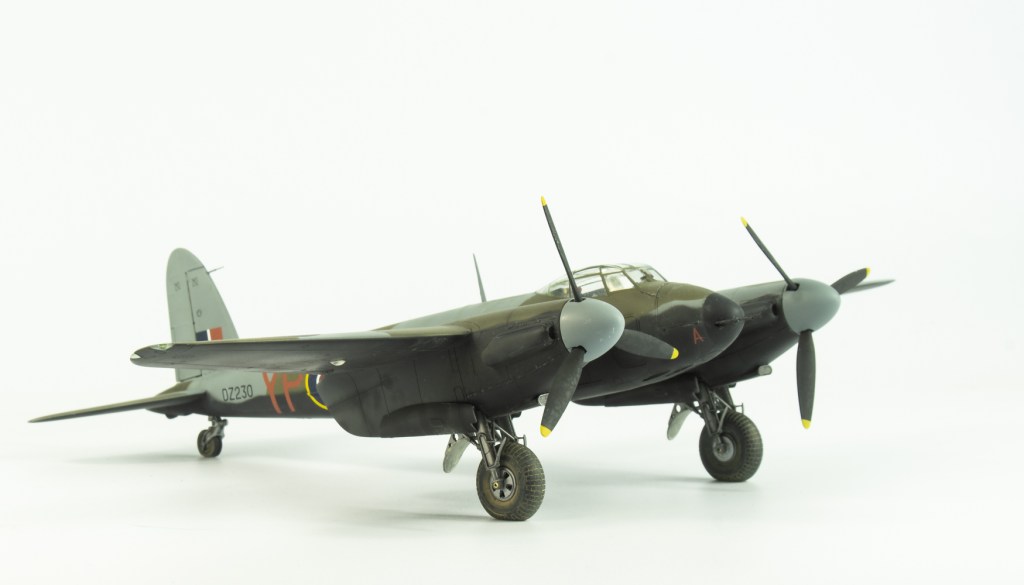
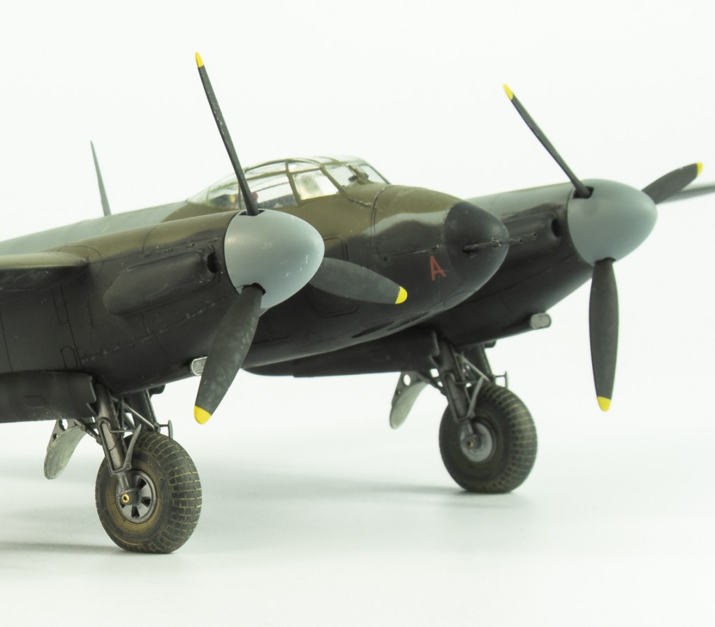
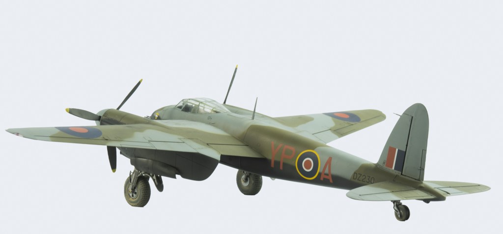
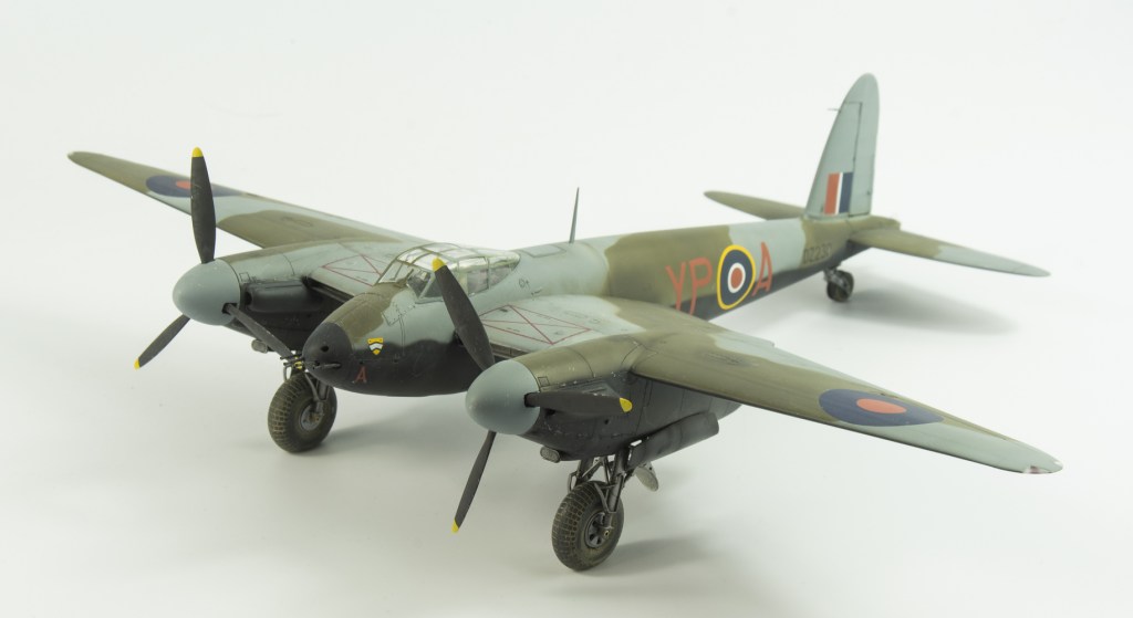
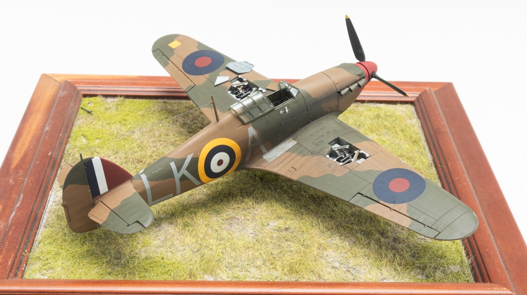
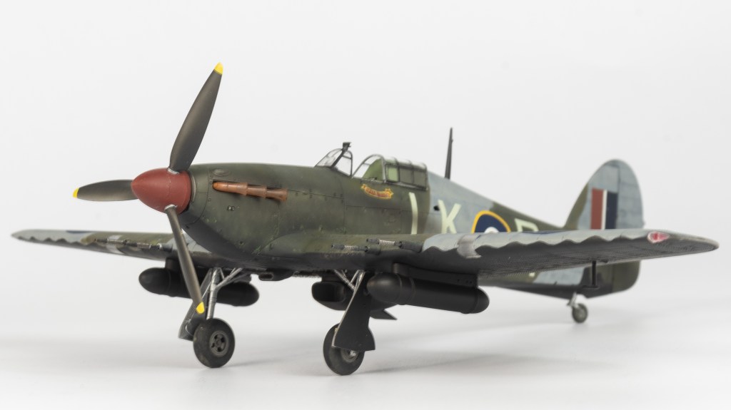
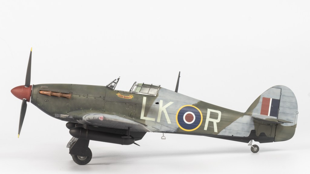
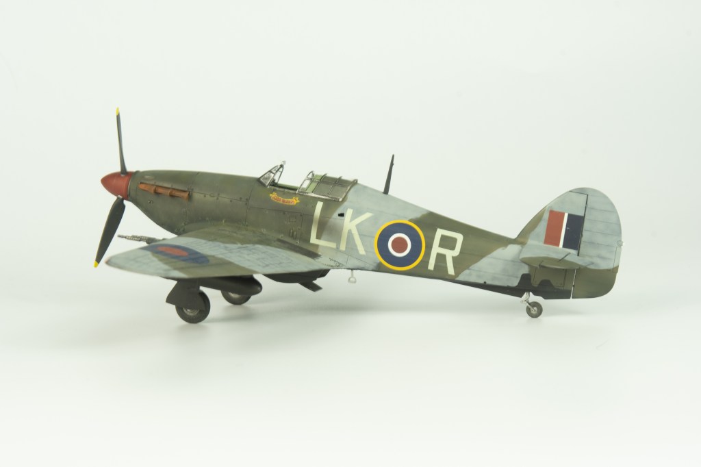
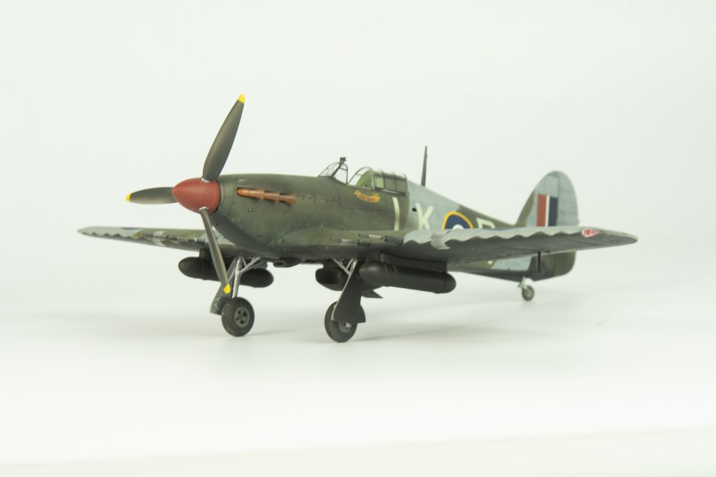
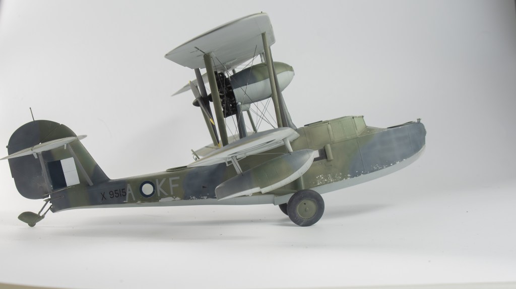
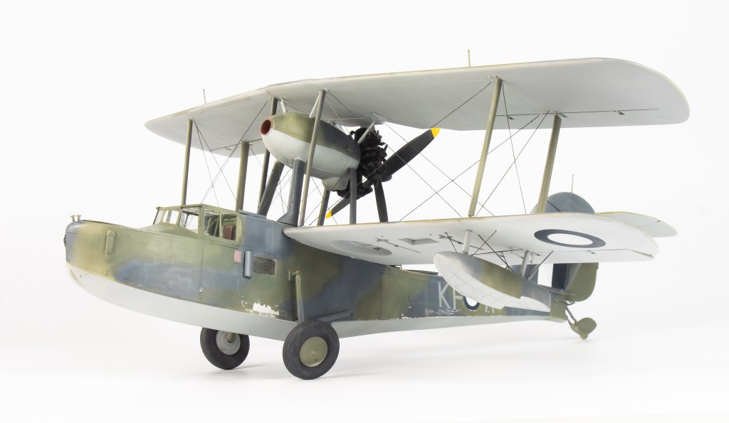
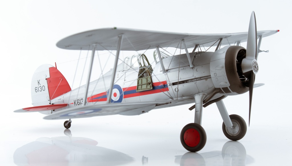
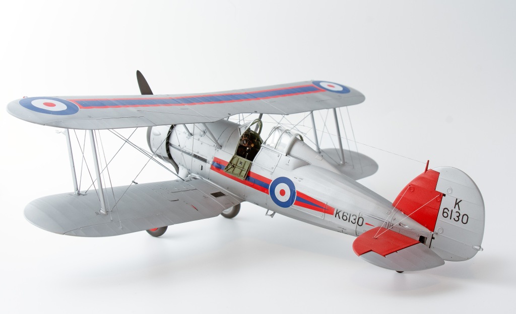
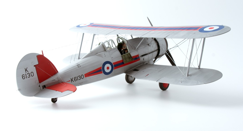
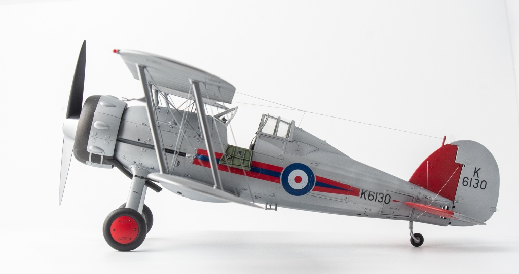
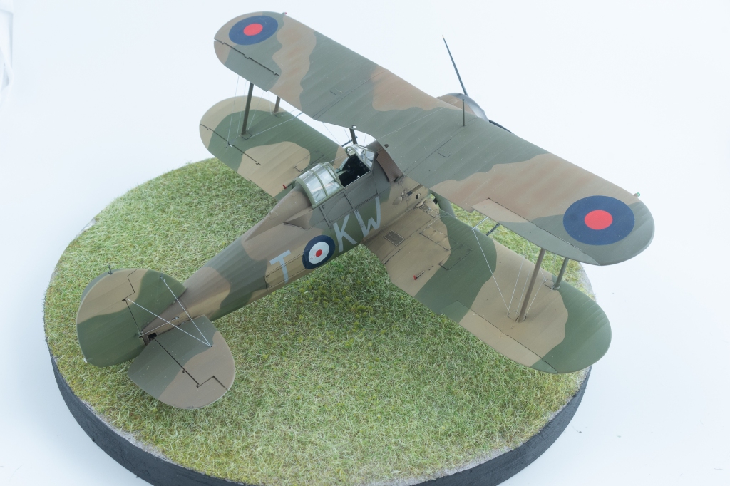
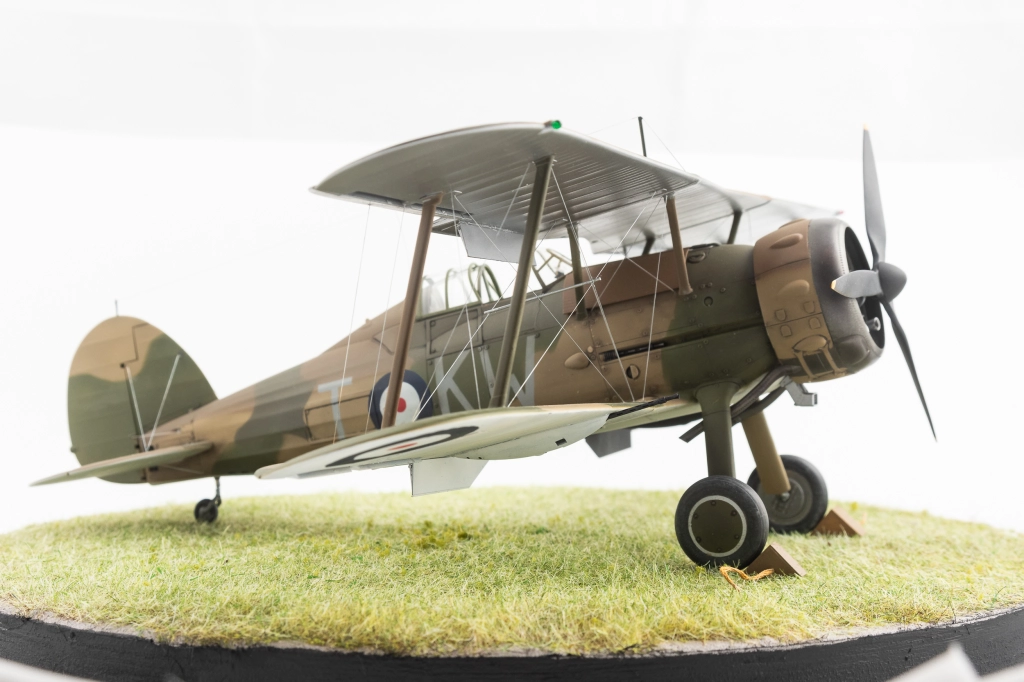
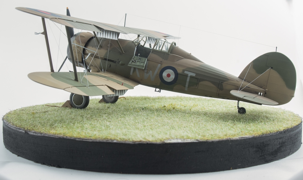
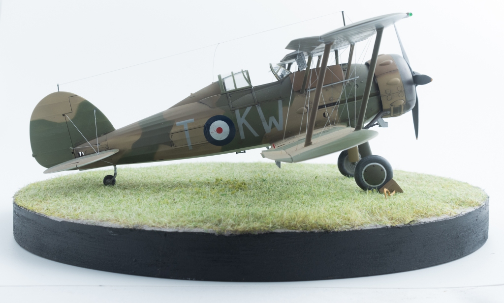
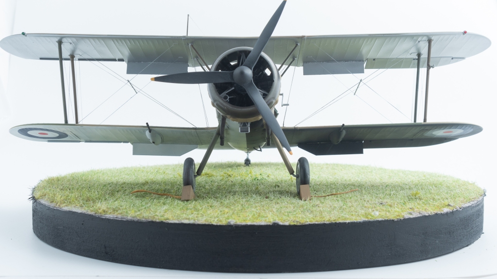
Eastern Motors Avenger MkII. 857 NAS. Royal Navy FAA. HMS Indomitable 1944


Leave a comment