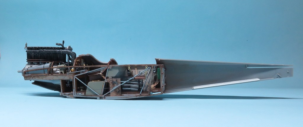
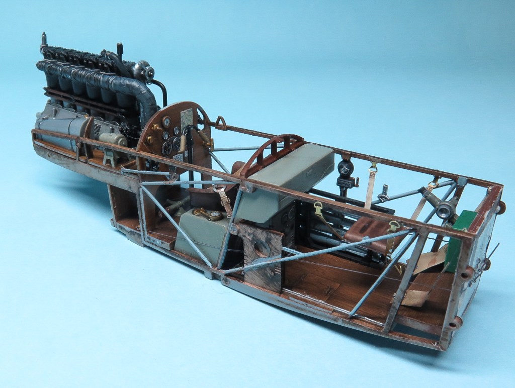
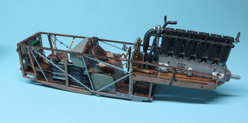
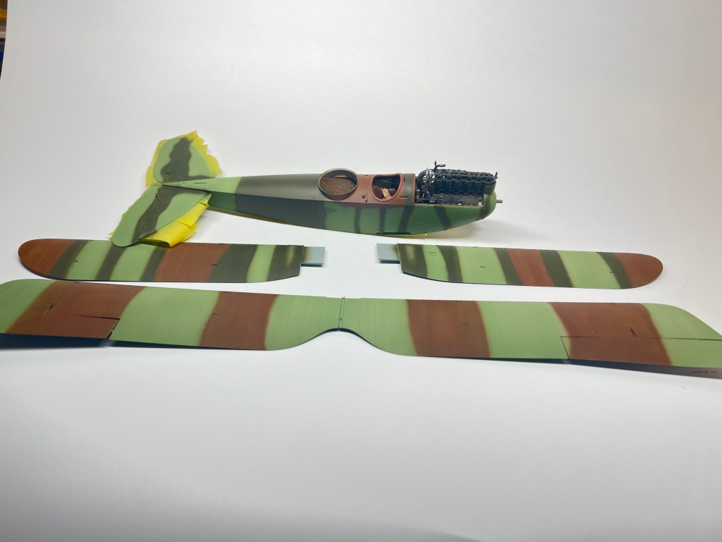
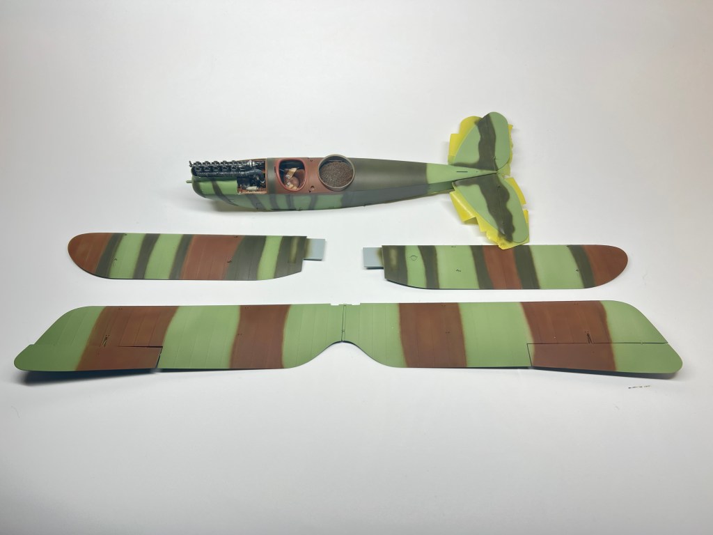
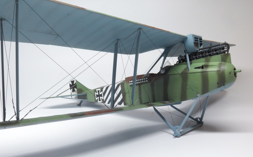
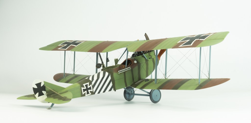
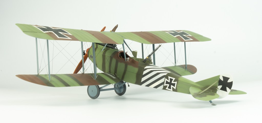
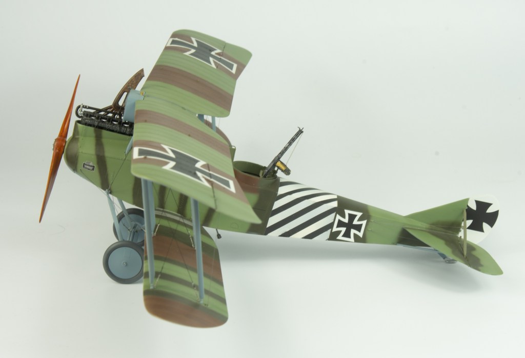
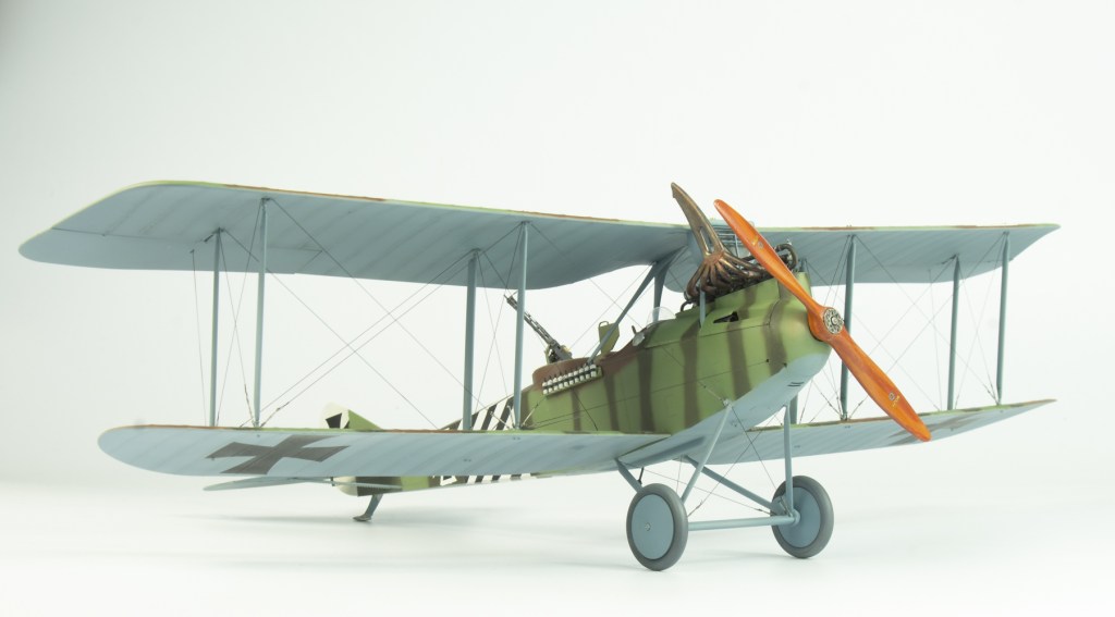
Im going to let the photos do the talking for this one, as it was pretty much a trouble free build, thanks to WNW quality engineering and production.
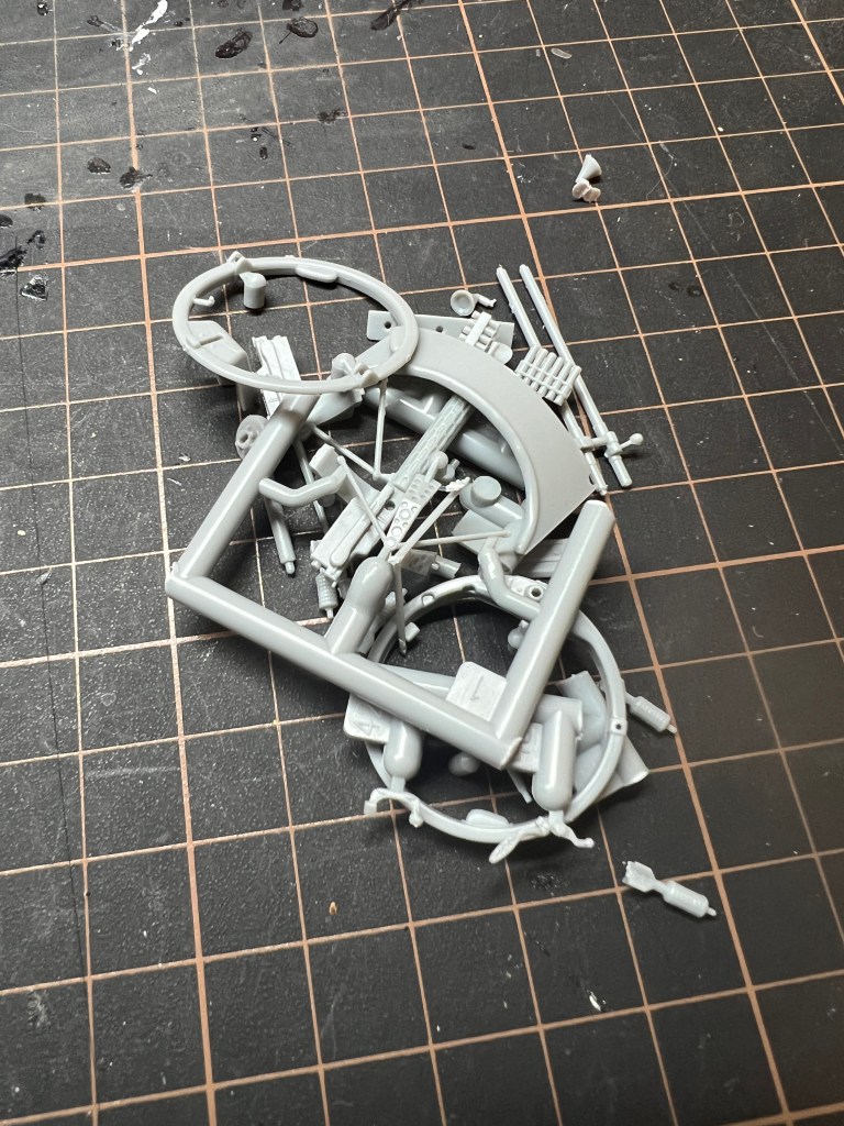
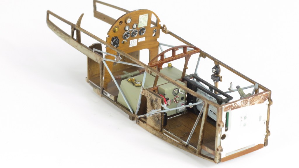
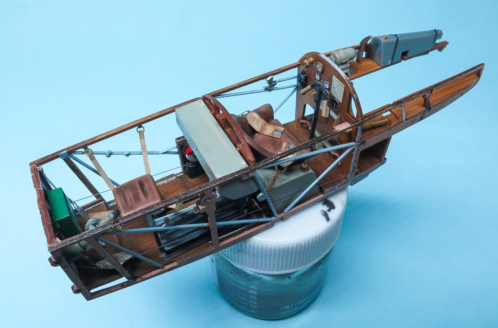
As with all my builds, construction started with removing all parts that WNW mark as “not needed”. This minimises the chance of using the wrong parts for your version.The cockpit and engine components were all prepainted prior to being assembled. the wood areas were base coated with MRP Middle stone, then the wood colour added with Burnt Sienna oil paint. Like all aircraft models, once the interior was completed, the airframe build up fairly quickly, more so when doing a WNW kit as all the wings are one piece. The ailerons were reinforced with bits of brass wire so as to provide more strength rather than relying on the very small glue area.
Painting and Decalling
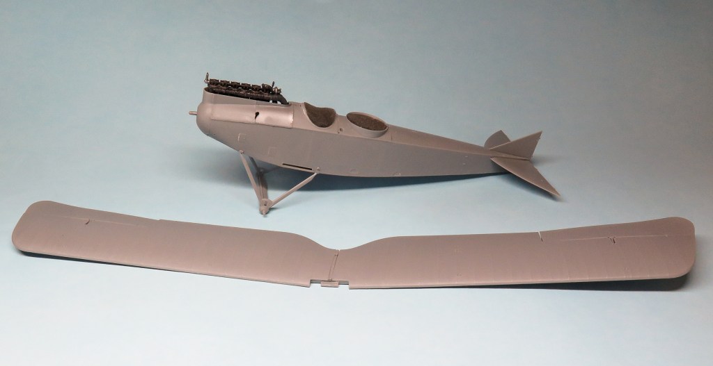
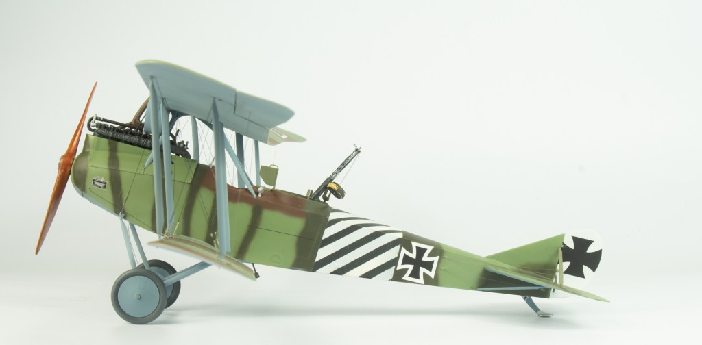
Painting was achieved on this occasion using Tamiya paints using the colours called out in the instructions. the exposed engine being first wrapped in GladWrap to ensure no overspray marred its finish
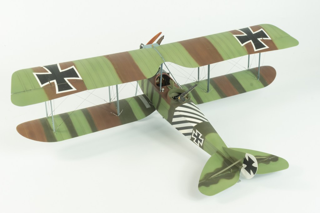
This would be a clean build, so no weathering was undertaken, however some shading to emphasise the ribs was done with some highly diluted black/brown airbrushed over the masked wing ribs. A tedious job, but I liked the effect.
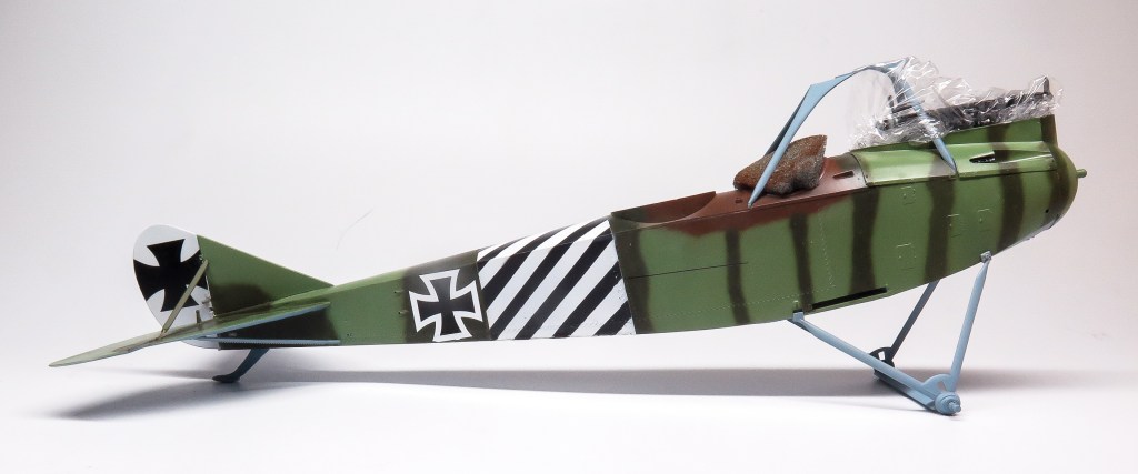
Although masks had been cut on my silhouette machine for the markings, only the stripes were airbrushed on, the decals for the national insignia being used on this occasion. Micro sol and soft ensuring they all hunkered down over the surface details. And just like that, we were ready for the GULP…….Rigging!
Rigging and Final Assembly
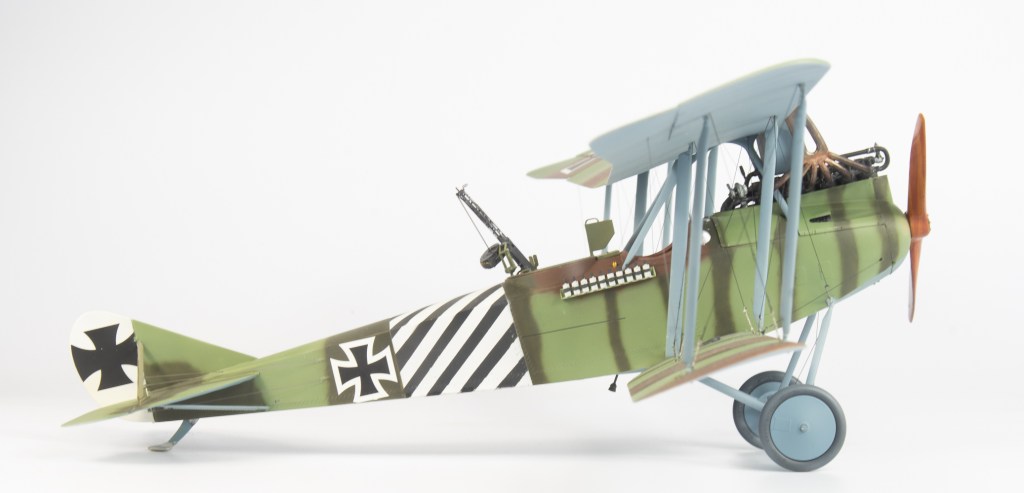
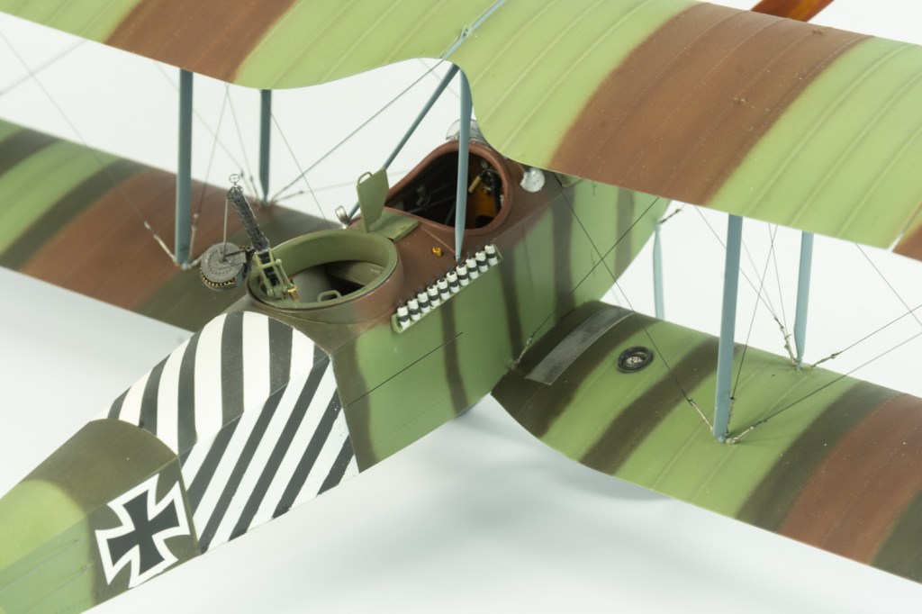
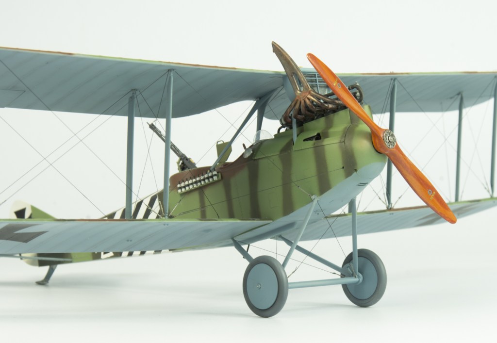
Although WNW don’t advise using turnbuckles in their hints and tips section – due to them looking overscale – my thought was they would at least make the rigging easier.
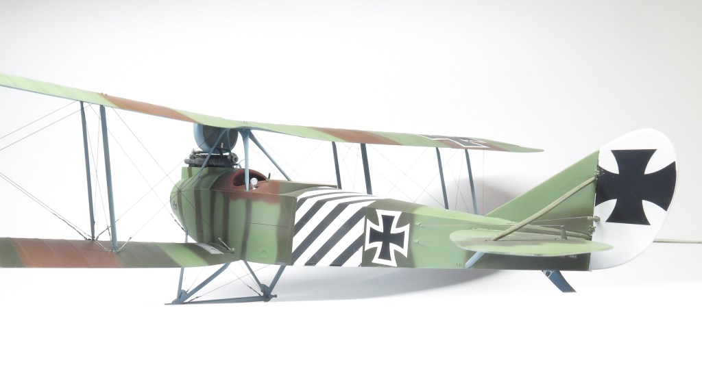
Plus, there were about 4 packs of Gaspatch turnbuckles in my aftermarket tub. Care needs to be taken when fitting these into your pre drilled holes that they will lie roughly in line with the rigging line. In the case of the Rumpler, turnbuckles were only fitted to the lower wing end points of the rigging wires. Model Kasten line was used rather than my usual EZ Line. It seemed to take to the CA glue a lot better than the EZ line, which in my experience just curls away when introduced to the glue. The Model Kasten line is also round in section, so you don’t get the twists that you do with EZ line. The downside however, is its a lot more expensive than the EZ line.
Using the turnbuckles allowed the rigging to proceed far more quickly and trouble free than any of the others methods Ive used to rig my biplanes this year. I did manage to cut the actual rigging line when trying to trim the line on a few occasions, but this was easily repaired.
Also in my AM tub were brass barrels for the Spandau and Parrabellum guns, but the kit PE jackets were rolled using a rolling set and looked convincing enough. They were finished using Humbrol Gunmetal which can then be gently buffed using a cotton bud to impart a nice metallic sheen.
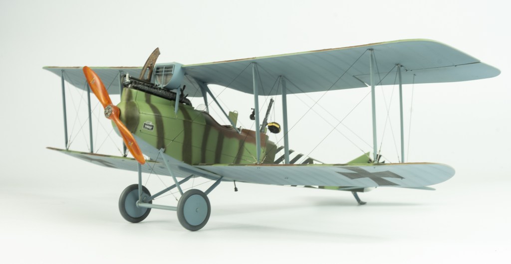
With the addition of the propeller and REXX exhausts – which should really have been added at the time of building the engine- she was done.
Conclusion
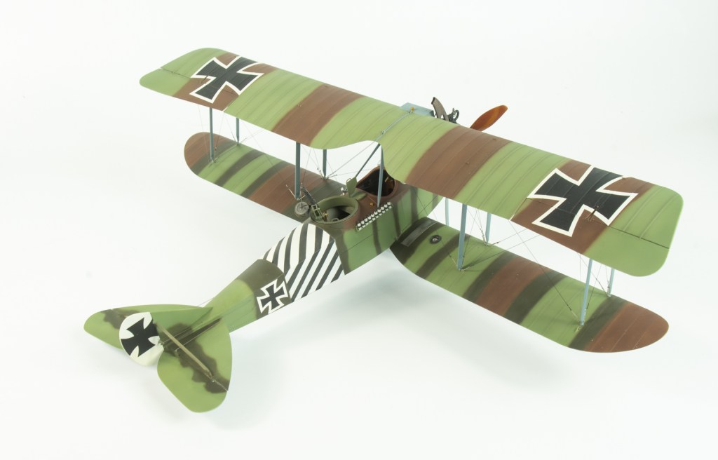
This was without doubt the most enjoyment Ive had from a model over the last couple of years. The parts fit is exemplary, as is the moulded detail and Wingnut’s instructions. Once you have the various interior components painted, the model builds up very quickly, and precisely.
If you are sitting on some WNW kits, so yourself a favour and build one≥. They are simply too much fun to build to have them sitting unbuilt in the collection, unless that is actually your thing.
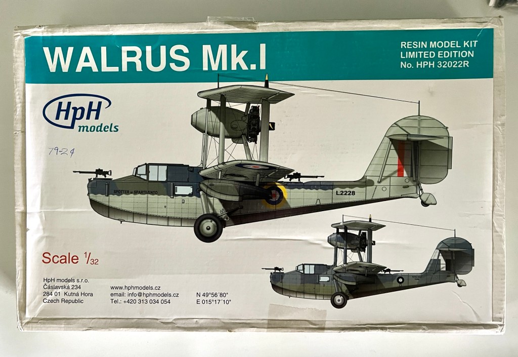
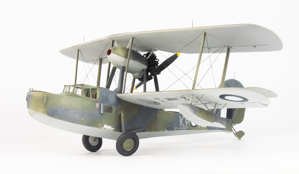
When this kit was first announced by HpH, I was immediately on board as the Walrus is a favourite of mine. The only kits in my preferred scale of 48 were the awful SMER and slightly less awful Classic Airframes kits, the superb Airfix kit still being 3 years away. A 32 scale Walrus sounded very epic. It was also very expensive!
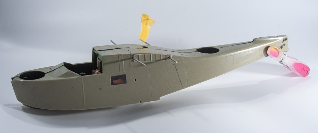
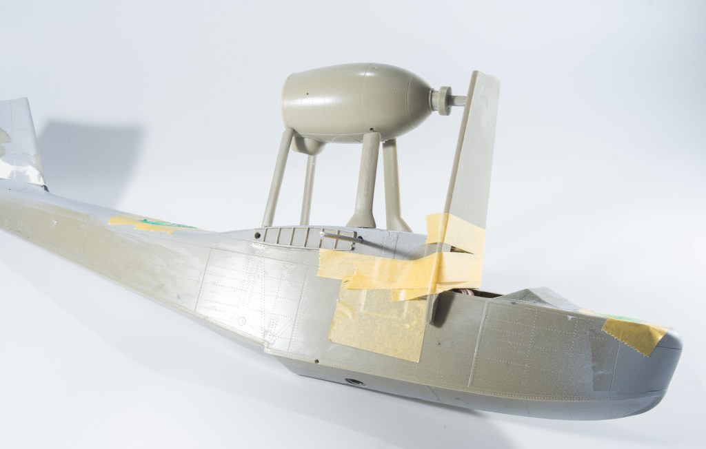
I was somewhat dismayed upon arrival of the kit to see the small resin parts had been cast attached to a sheet of resin. Separating the parts was going to require quite a bit of sanding!
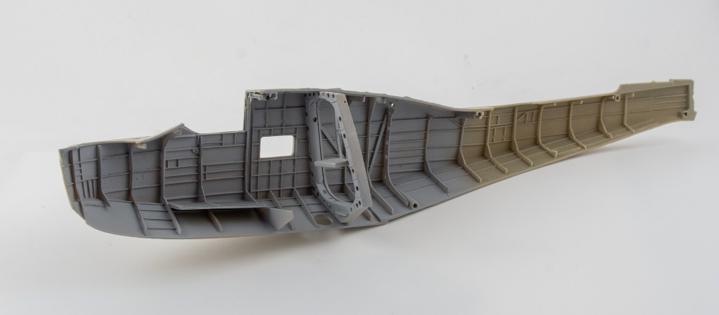
Aside from that, the main airframe parts looked to have been cast very cleanly and with excellent detail, the fuselage being fully riveted and the flying surfaces being cast in solid pieces with rib detail that mimicked the sturdy construction of the real thing. The bow section had been marred by the rough removal of the casting block at the factory leaving a ragged gap when both fuselage halves were dry fitted together. Instructions were on a CD which I printed out, so as to make them more accessible on the bench. It is handy though to keep the CD handy as you can zoom in on the parts to help identification. Whilst the parts are numbered in the instructions, the actual parts aren’t. Numbers on casting blocks would have helped greatly in assembly. This would have to be one of the most complete kits on the market, with decals , photo etch, masks and even HGW fabric seatbelts all included in the box.
Construction
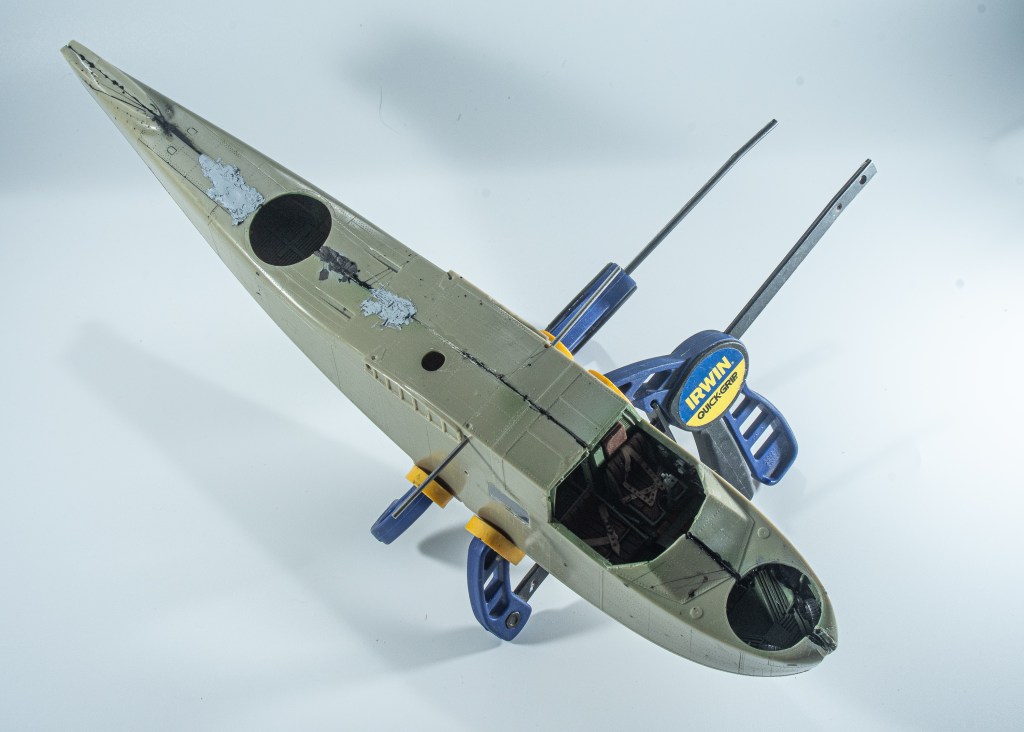
The first order of business was to straighten the two fuselage halves. Although I had taped them together many years ago to preserve their shape, they had still developed a few warps. These were straightened by the simple expedient of dunking the fuselage halves into boiling water until they naturally returned to their original state.
Construction was able to be commenced straight away, thanks to me having removed most of the resin parts from their backing a few years ago during downtime at work
Much sanding was involved, the parts either being hand held or taped to a small piece of aluminium angle whilst sanded against a sheet of wet and dry taped to a flat surface. My recollection at the time was a few parts got damaged but looking at my work now, far less than I remembered. Yay for me!
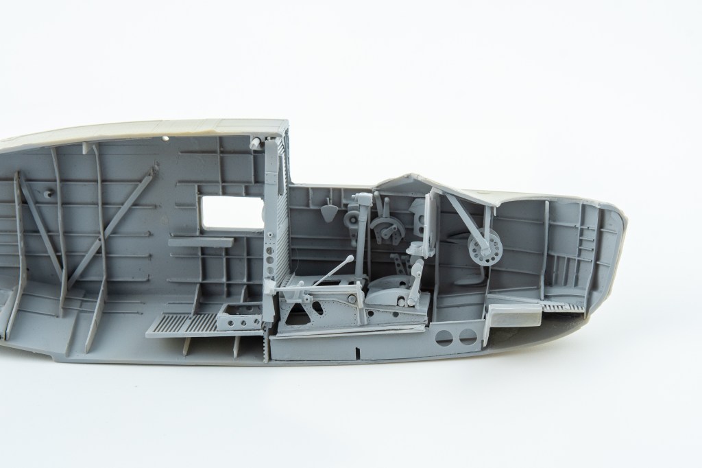
The interior is VERY complete, with a full cockpit, radio operators and navigators station included. The only thing missing was the run of control lines along the fuselage, which of course could be added by the modeller. The bell cranks leading off the control column and rudder bar are provided though, ready for you to connect the lines to.
Id suggest adding the side windows first whilst you still have good access . If the resin flash from the window openings is carefully removed, the resin windows should be a push fit once the window opening corners are squared off
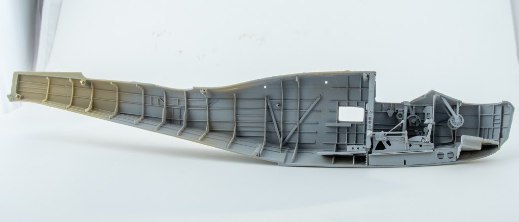
To keep the build momentum going an early decision was made to only build the visible items. So into the spares box went the radios, the operators seat, and a few other bits and bobs that would never be seen. The roof trellis was replaced by a piece of plastic card that formed a tab to help align both fuselage halves.
There are side windows which you can see flashes of the navigator’s table through, but that’s about it. Given this, adding the radio sets, and all the other mid fuselage fittings seemed pointless as they would be invisible on the finished model.
So, only the parts around the gunners openings were added, such as spare drum magazines, ribs and floor sections.
Constant dry fits of the fuselage halves ensure they would mate without any of the ribs fouling. There was a bit of filing required, and snipping of various ribs needed throughout this process. All in all, though, everything went fairly well, with the various components locating nicely, apart from the floor which required new slots cut for the ribs to fit into. Tedious but easily achieved by holding the floor up to the ribs, the new positions for slots marked and then cut in.
To help matters, ensure you add the side windows early before any of the other parts and that you glue all the bulkheads to the same side. I didn’t do either of these things and it complicated assembly a little bit. Ensure you get the snuggest fit you can with the main bulkhead against the interior wall. Mine also needed sanding a fair bit to reduce its width.
Once this was in place, 2mm holes were drilled through the depressions HpH had thoughtfully added. K&S stainless steel rod was used. Lines were marked out on the wings to ensure the holes were drilled perpendicular to the fuselage. With as much of the interior as I wanted installed and painted , the fuselage halves were now joined. It was not the best join, with several steps in the keel and one behind the canopy. These were fixed by cracking the join and reglueing the area, one area at a time. This worked quite well with all of the steps being eradicated.
The entire seam required filling with super glue and repeated rounds of sanding and priming to remove all trace of the seam. The main area being the top of the fuselage between the rear gunners area and the cockpit. The area immediately behind the cockpit required its raised detail reinstating with plastic strip as my judicious sanding had eliminated it. The aforementioned tab of thick plastic card under the roof join ensuring that seam didn’t crack open with all the required sanding.
A spot primer coat of Mr Surfacer was then applied and the rivets reinstated with a Rosie Riveter riveting tool.
Although the holes for the wing spar were drilled where HPH indicated. Looking at the model in plan view revealed the wire was not exactly at 90 degrees to the fuselage centre line. Redrilling it would have caused a loss of the structural integrity I was hoping for, so it was left as is, my thinking being the matching hole in the wing could be drilled at an angle to compensate.
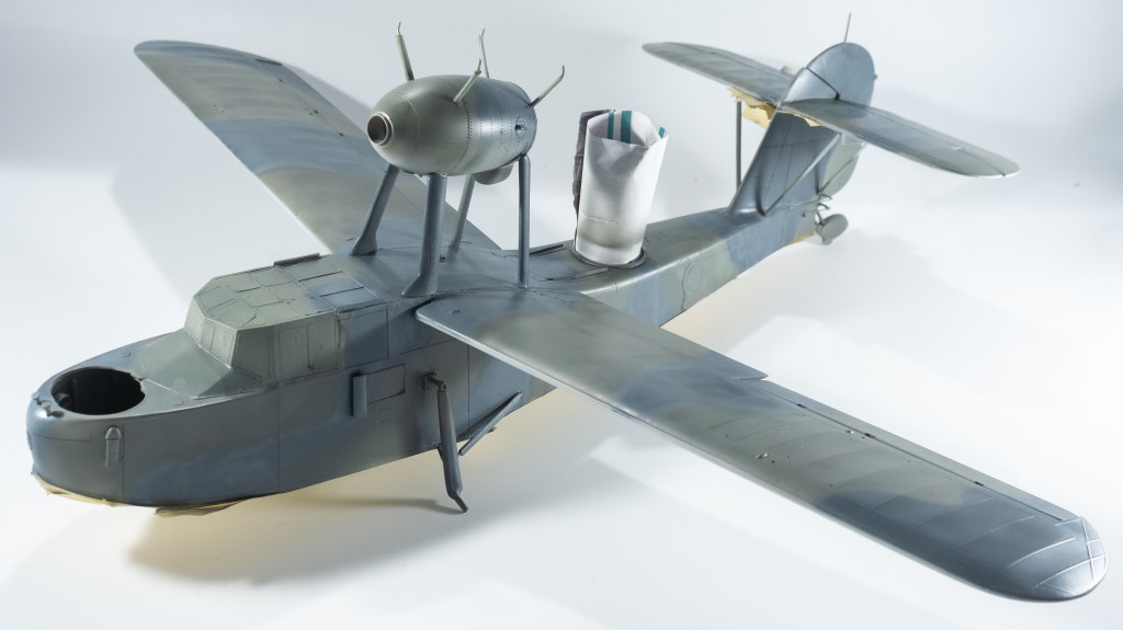
Next on the list was the fitting of the engine nacelle. HpH providing a helpful jig to aid in its alignment
HpH provide dimples for where the strut location holes need to be drilled, however no advice as to what angles the holes should be drilled at. It is left up to the modeller to determine by studying the walkaround photos included in the instructions.
To me, this is one of the areas where HpH could really improve the modellers experience in building their kits. Yes, I know HpH market to the advanced modeller, but this does not absolve HpH from providing detailed instructions to assist in making their kits an enjoyable build. This is a key part of the build. The nacelle provides the base to which the top wing centre section is attached. Getting the struts at the correct angle here is imperative to getting the geometry of the aeroplane correct. Given you are joining a centre section which needs to be square to an offset nacelle, strut placement and angle is critical. No assistance in the form of diagrams, pre drilled holes is offered by HpH though, the photos in the instructions being less than helpful.
Its these kinds of things that don’t make building the kit as enjoyable experience as say for example, a Fisher Models kit. Anyway, the nacelle was fitted. 4 of the 8 struts needed fairing in to the nacelle with Milliput as they were a little short. I was concerned my nacelle was not forward enough, a point that was reinforced later when fitting the propeller as it fouled the wing trailing edge. Oh well!
The next step was to fit the rather large tail unit. The tail fin is a separate part and when test fitted, had quite a large step on one side requiring building up the side of the fin with milliput. Rivets and panel lines were then reinstated . On top of the vertical fin sits the tailplane. In the kit they come as right and left halves, one of mine had a casting flaw that left a mark which would have been incredibly hard to sand away without destroying the rib detail. All the tailplane parts need to be pinned to each other to ensure maximum strength. There was no real difficulty in this stage, just ensure everything is square. Mine looked square, that is until I got the wings on!
There are two bracing struts each side. Dimples for drilling are there on the fuselage, but not the stabilisers. Consequentially, my struts were fitted to the tailplane one rib too close Of course they had been soundly glued and faired in before this was realised. I didn’t pick this up until comparing the model yo photographs of the actual aircraft.So they were painstakingly unglued, holes redrilled and the struts relocated one rib further out. I was starting to not enjoy the Walrus.
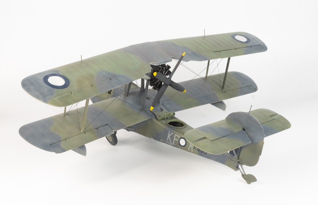
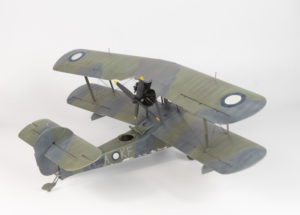
Wings were added next, again not as neat a fit as the dry fits suggested. This was purely down to my imprecise drilling, rather than the kit, as dry fits had shown a step and gap free join several times. The upper wing is quite a heavy sizeable assembly when the outer wings are glued to the centre section. 2 part epoxy was chosen for its added strength. Adding the upper wings to the struts took several goes to ensure everything was straight. My top wing has got a slight twist in it due to the top nacelle struts being out of line, thus causing the wing centre section to not be square to the longitudinal axis.
Rather than continue with a blow by blow account detailing all my errors, below is my suggested assembly sequence for anyone else attempting this model.
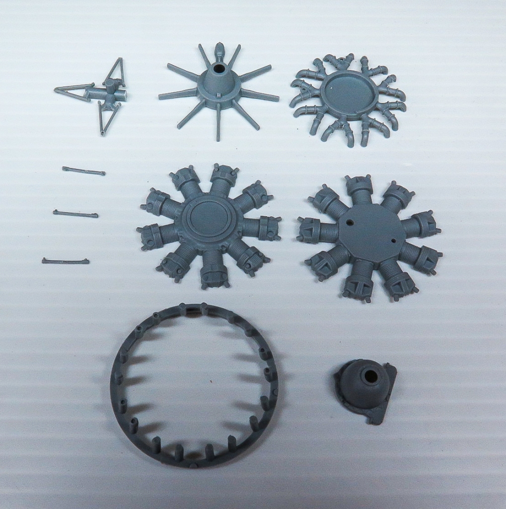
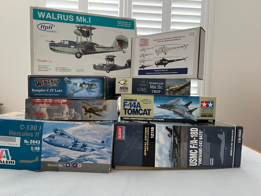
Ensure all contents of kit match the photo of kit parts
Drill holes for spars in wings and fuselage. Test fit often. Ensure all holes line up and are perpendicular to fuselage centre line. Do not add upper wings to centre section yet.
Add the main bulkhead which will have the wire spar pass through it and drill this.
Assemble fuselage adding as much of the interior as you desire, bearing in mind much of it will be invisible. Ensure canopy will fit.
Pass wire spars through before closing fuselage. It’s a lot easier than afterwards!
Build and add tail unit ensuring everything is square.
Build up engine nacelle as complete unit with lower struts, ensuring by repeated dry fit it will be able to be added later. Use supplied jig to ensure it will be sitting in correct place with struts angled accordingly. Drill holes for the nacelle rigging.
Ensure lower wings are a good fit. Do not attach them yet.
Use the lower wings as a jig to assemble the outer floats but do not attach them at this time. Drill all holes for rigging.
Add the upper nacelle struts to the upper wing centre section, ensuring all your struts are at the correct angle to ensure the centre section remains square to the fuselage centre line. This is vital in ensuring your model will have correct geometry. It will also take lots of trial and error , remember that nacelle is offset, but the centre section needs to remain square. The instructions don’t really illustrate the position of the struts at all well, You want the angled bits of wire plugging into the upper wing. Glue the struts to the nacelle, but not the centre section at this stage
Disassemble the model into subassemblies of fuselage, nacelle and centre section
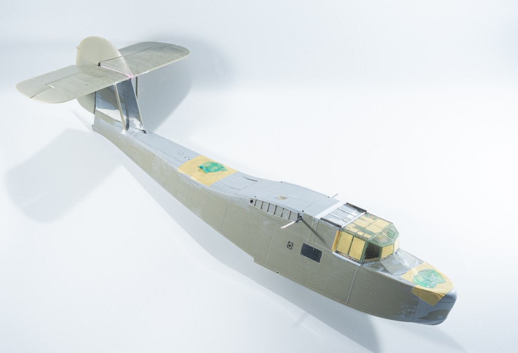
Add canopy. You will be annoyed to find the supplied masks are all undersized!
You can now paint the fuselage and nacelle and wings and I would go as far as even decaling.
Glue nacelle to fuselage and add rigging.
Add floats to wings, rig the floats then add wings to fuselage.
Add outer wings to centre section, glue struts in place and into wings.
The tailwheel/sea rudder should be added last to save breakage, mine must have snapped about 3 times despite having a steel wire core.
Ah, the benefits of hindsight. I’m sure my build would have gone a lot easier if it had been tackled this way.
By the stage of adding the upper wings I was completely over the model, in fact a couple of times I simply just did not want to sit at the bench.
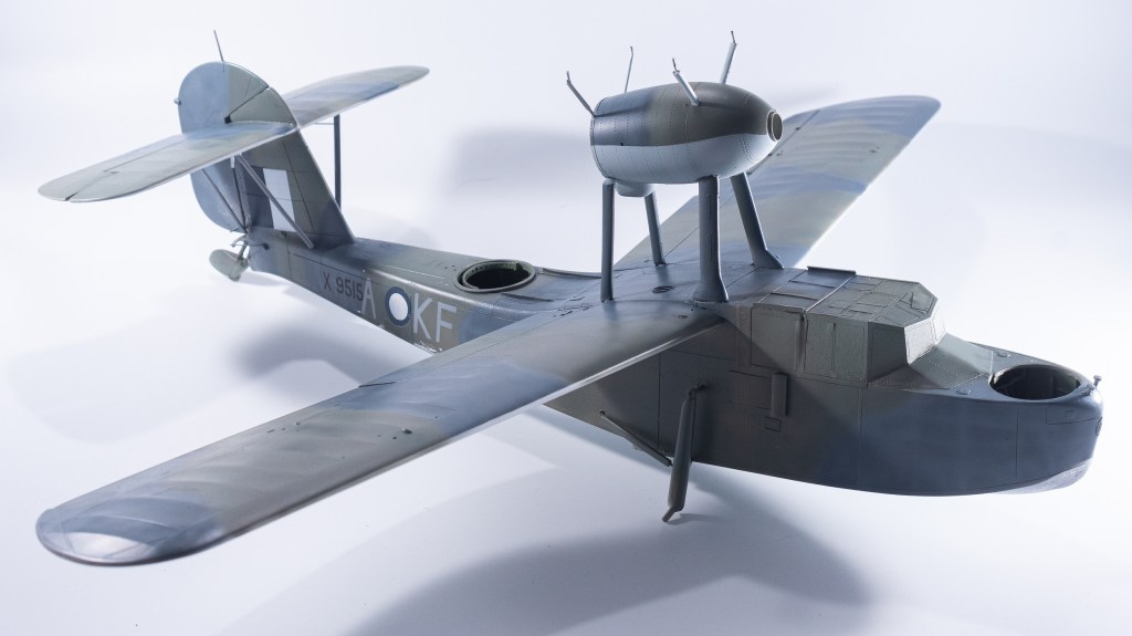
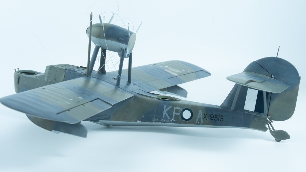
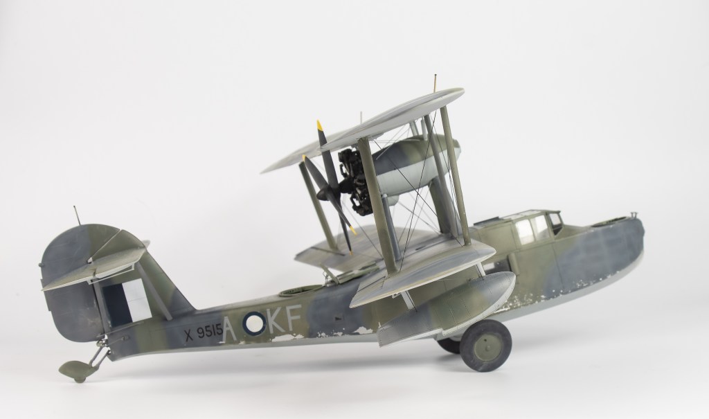
The decision was made to finish the kit to the bare minimum standard. My initial vision was a battered weatherbeaten aircraft, but at this stage, simply did not have the strength to invest any more time than was needed to get a basic paintjob on the model. For the above reason my model’s weathering is limited to some chipping along the hull using the hairspray technique. It was left at that. The weathering may get revisited at some stage, but probably not.
Paints used were MRP for the top surfaces and white Ensign enamel for the underside Sky Blue. Enamels are not my paint of choice these days, but this sprayed beautifully, but boy did it pong!
Anyone that says lacquers smell worse than enamels are kidding themselves. HpH threw in one last annoyance with their provided canopy masks all being undersized, necessitating new masks being cut from Tamiya tape. I was by now thoroughly over this model and just wanted it off the bench.
Masks for the markings were cut after scanning the decal sheet for the Airfix 1/48 scale kit.
Rigging was fishing line. Holes were drilled right through the upper wing so that the line could be pulled taut, the holes then being filled. It would have been better to drill right through the bottom wing, but this is the kind of model you simply just don’t turn upside down if you can avoid it. It weighs a ton, turning it upside down would be just inviting disaster.
With the rigging done, all that awaited was the wheels being added. This was accomplished without incident, and with that, the Walrus was done.
Conclusion
I have very mixed feelings about the finished model. It is nowhere near my best work. In the haste to get it off the bench, several compromises were made, especially in regard to the finish. Parts such as bomb racks and the machine guns were left off, although photos do show this machine with no gun armament. Despite this, the finished model is a beast, it captures the nature of the Walrus like no other scale can, and looks very impressive in the cabinet. I love it. HpH have made an excellent kit, although some details like landing light and wingtip lights are missing. The model certainly is not fun to build.
Strangely it has not lessened my desire to build the 2 other HpH kits in my stash, these being the Hornet and the Helldiver. What it was responsible for though, was me deciding to sell just about all of my bigger 32 scale kits. hese big, complex builds in my stash, so onto the For Sale pile they went, and I feel a lot better for it. Most of them have already been replaced with the same subjects in 48 scale. My cabinet thanks me.
Now for a lie-down and a Tamiya kit!
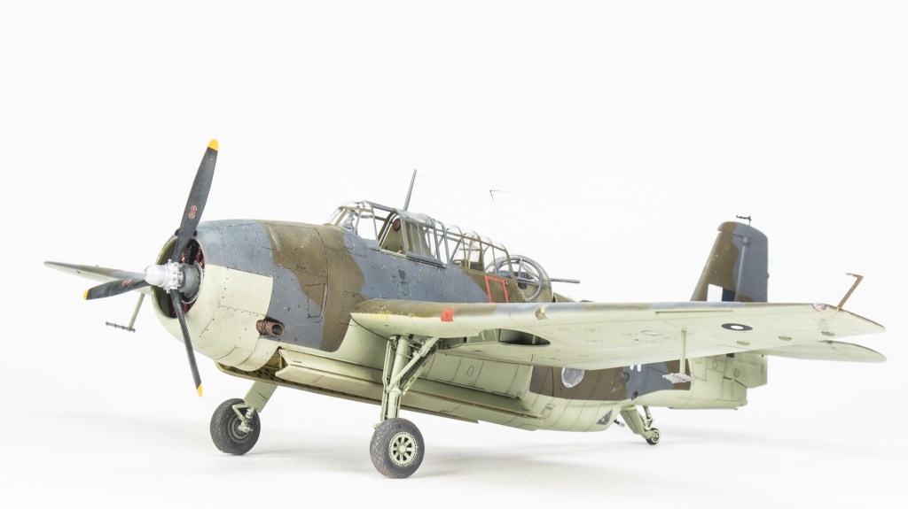
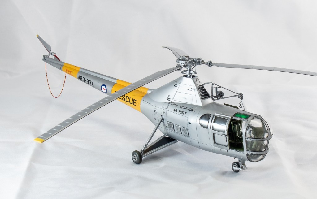
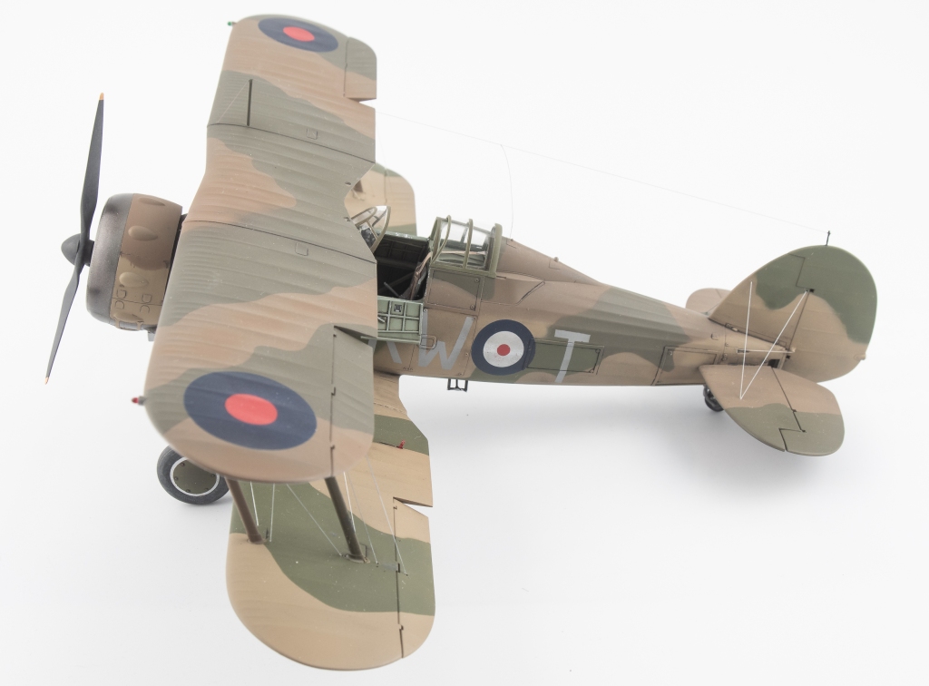
Supermarine Walrus MkI 5 Communications Flight. Royal Australian Air Force. New Guinea 1943
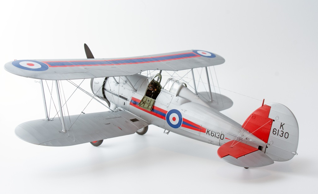
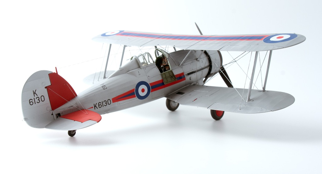
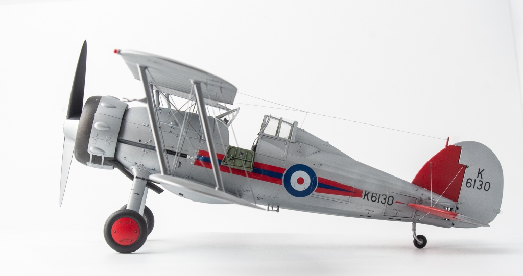
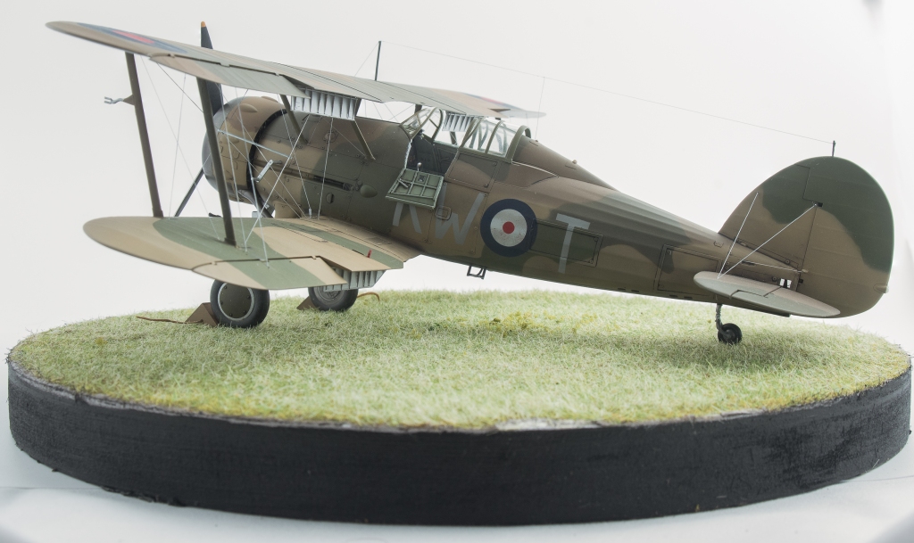
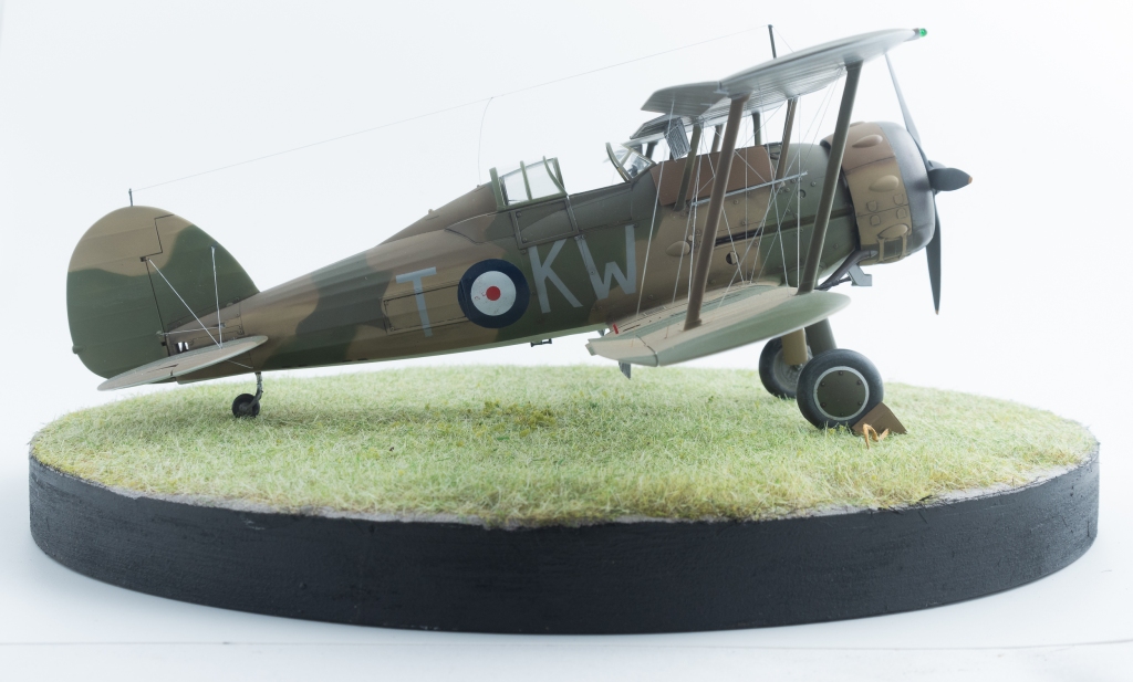
I enjoyed my other Gladiator so much, I decided to build the second one in the stash rather than selling it as was the original intention.
Even without considering the “foreign” air forces, such as Sweden or Finland one is spoilt for choice with Gladiator schemes, do you do a silver interwar one, or a camouflaged war RAF example? Then there are the Sea Gladiators as well. My previous model was finished in early war RAF camouflage, so this one would be a silver interwar RAF example.
Construction
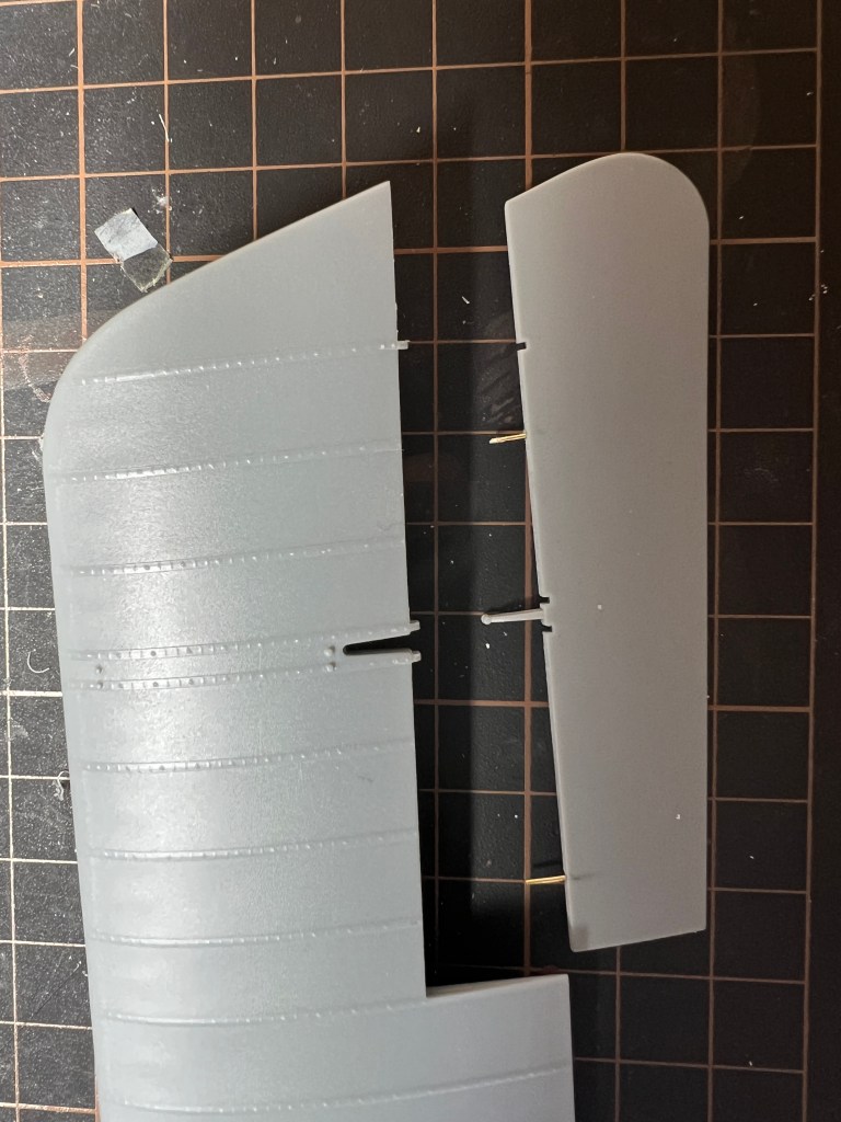
To take a different path from the usual “starting with the cockpit”, the rudder, stabiliser and elevator halves were first glued together so that they would have time to properly set up and allow any glue shrinkage to show itself.
With this done, construction returned to following the steps outlined in ICMs instructions, starting with the cockpit. ICM provides parts that when built up result in a reasonably busy looking cockpit.
Of course, the builder can improve on this. In my case I included some simple additions and refinements starting off with wrapping thin copper wire around the spade grip of the very plain looking control column. A brake lever, cam and the brake line were added from scrap plastic and solder.
Map cases were built up out of plastic card, and the slots on the throttle quadrant deepened with a Trumpeter scriber before new throttle levers were added from slivers of plastic card topped with blobs of paint.
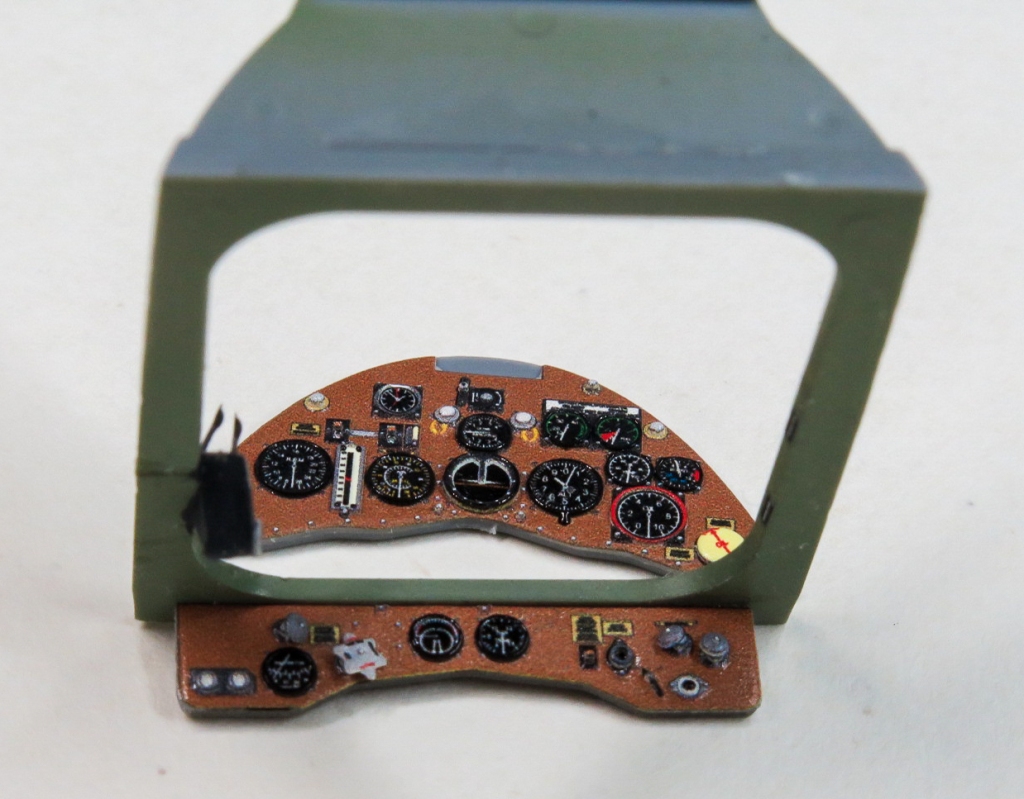
Quinta 3D Decals were used to replace the instrument panels and seatbelts. The kit compass pedestal was replaced with a better detailed Quickboost item.
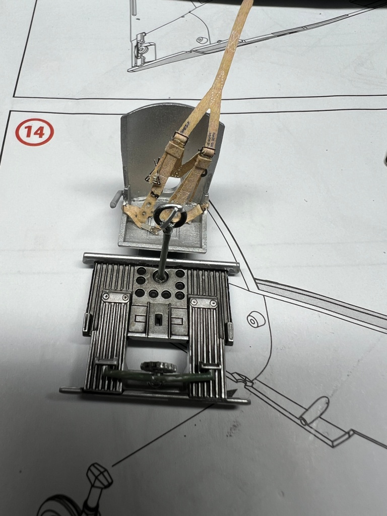
There is an ejector pin in the seatback that needs to be filled and the gunsight requires the clear reticule adding. A punched disc of clear plastic did the job here.
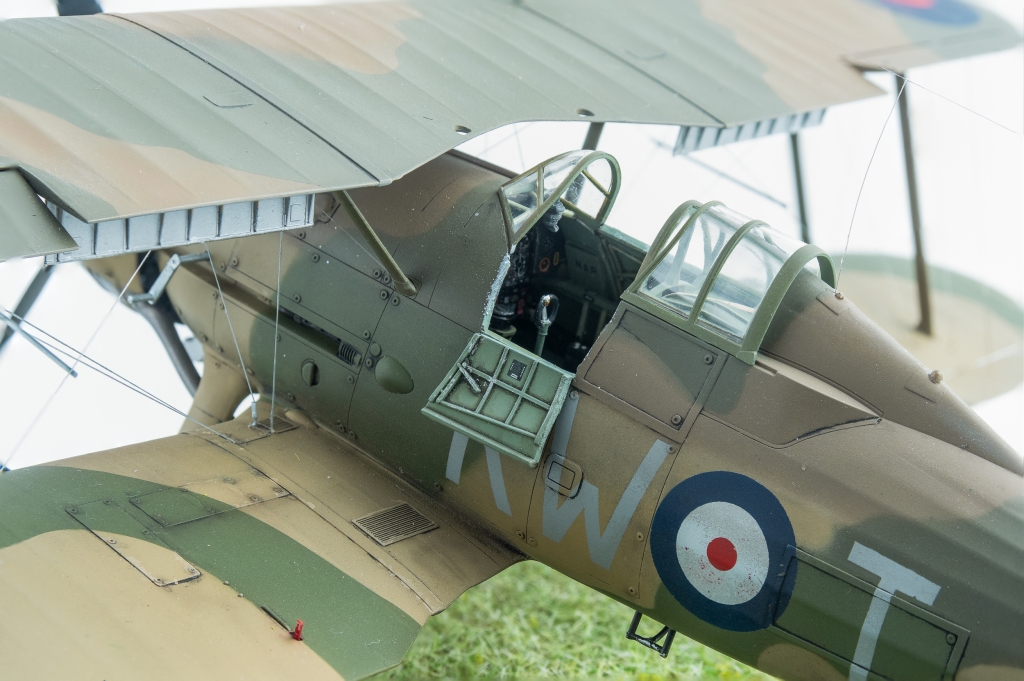
Once the cockpit shelf is added, you really can’t see too much into the depths of the cockpit, even with the cockpit access doors opened. Speaking of shelves, to better replicate the real item, the rear shelf behind the pilot (part C22) was cut down to leave just the central beam. To my eye, this really adds to the open framework look of these 30’s era aircraft.
If you wanted to add detail to the now visible interior behind the pilots seat, frames and a radio could be built up from card and strip. I didn’t bother as my canopy will be open and sitting over the top of the fixed canopy section, so hopefully, that empty space will not be too visible. Finally, the machine gun barrels were cut off, as these would be replaced by brass Master Detail barrels once all painting had been completed.
With the cockpit painted and detailed to my satisfaction, the fuselage halves could now be closed. This was achieved with Tamiya Extra Thin Glue which was liberally applied allowing the excess to ooze out to fill any gaps.
The two halves fit tightly. The lower insert…..not so much. That said the gaps here were minor and were eradicated with CA glue mixed with Mig Ammo Steel metallic pigment. To me the pigment seems to make the CA slightly easier to sand and also has the benefit of colouring the glue so you can see what you are sanding!
The fuselage was then mated to the lower wing assembly with some filler required to blend in the rear join. A result of the soft ICM plastic the wings are alarmingly flexible but adding the struts and top wing will hopefully add some rigidity.
ICM would have you rely on a small diameter plastic peg, inserted into a hole in the fuselage to hold the horizontal stabilisers in place. Given the soft plastic, this would likely end in tears so the pegs were cut off and a suitable diameter brass rod used to provide far more strength. Even more fortuitous is that the real Gladiator has a small gap here between the fuselage and stabiliser. While you have the brass rod out, the tailwheel strut can also be cut and replaced as this is another weak area of the model.
With this done, a complete airframe and top wing sat on my bench awaiting primer. Prior to priming, a No. 77 drill was used to open up all the rigging points as I intended to use EZ line for the rigging. Once all holes were drilled, the struts were cleaned up and attached in their respective positions.
Next up was the engine. Again, ICM have done an excellent job of portraying the Mercury engine. When completed it looks quite busy with its cowling support braces and cooler intake tubes. Quickboost do make one piece air cooler intake tubes that are slightly better detailed however I didn’t use them on my model as the kit ones looked fine to my eyes. The instructions here were slightly confusing, but eventually I worked out you have the option of building the cowling closed or open. If building the closed version, do not add the cylinder heads, parts D14 or exhaust pipe “plates parts D21 and D22.
In a perfect illustration of the pre planning that goes into all my models, it was now that I decided the model would look better rigged with the AIMS PE Bracing wire set rather than the EZ line. The reasoning being that the PE would better represent the flat RAF wires that were used on the real aeroplane. The set was promptly ordered from AIMS in Hungary. Post from Hungary to Australia takes about three weeks.
Painting and Finishing
While waiting for the PE bracing to arrive the model was painted. A primer coat of Mr Surfacer 1500 revealed a few seams, mainly around the lower fuselage insert. These were eventually dealt with, some which required multiple attempts!
The fixed tail surfaces and wheel hubs were then given several light coats of SMS red. This was then masked off and the remaining airframe, tail control surfaces and cowling got the Tamiya LP11 treatment with the model being rubbed down with fine 8000 grit sanding pads between coats.
Once the AIMS rigging arrived a careful perusal of the instructions revealed that AIMS wants you to remove the moulded inspection hatches from the wings so that they can be replaced with PE items. The idea being that the hatches are placed over half the hole drilled for the rigging to make a slot for the PE bracing wires.
Whilst the AIMS instructions provide clear photos of an actual Gladiator to assist you with placing the PE bracing wires, it would have been more useful to have been given precise measurements as to where to drill the holes to accept the wires. Of course, this meant that some of my previously drilled holes were in the wrong spot so these were carefully filled and redrilled all the time dodging previously installed struts.
In the end it all looked a bit messy, so the decision was made to strip the model using Mr Thinner and repaint. This took me back to where I was 3 weeks prior. I would complete far more models each year if I didn’t have to do so much twice or three times to each model!
On the other Gladiator build I had used a 1 Man Army mask set for the stencils and these had really impressed me sot they were put to work again. If you have not seen these sets, they are laser cut masks for not only the national markings, but also all the maintenance stencils. As the surrounding area needs to be taped off to prevent overspray, all these markings were sprayed prior to applying the decals as I did not want to be applying Tamiya tape over decals. SMS Super matt Black was used to spray all the stencils, and then the masks removed.
The decals are by Aerocraft Models. These performed very well, laying down with the aid of Microset and Microsol. However, (there’s always a however!) Aerocraft do not give you handed fuselage Sqn flashes.
Both flashes provided are for the port side fuselage. To apply the flash correctly to the starboard side and have the serial read correctly, the modeller will need to cut the serial from the flash and apply it separately so it is correctly orientated. If applied straight off the sheet without modification your serial on one side will be upside down and back to front.
The front of the stripe is also angled to follow the panel line there, and if not corrected, this will slope the wrong way also. Aerocraft helpfully supply some spare striping in both red and blue, and this was used to reverse the angle of the flash on that side.
A sealing coat of SMS flat varnish was then applied over the whole model. Once dry, panel lines were given a wash using Tamiya dark grey panel line accent with the excess being wiped off using white spirits. Removable panels were outlined with black wash.
I wanted something different from my usual weathered finishes so on this model I went with a cleaner finish.
The exhaust collector ring and exhaust pipes were painted in a mix of MRP Exhaust Colour and SMS Dark Bronze. If using the kit exhaust pipes, they will need their ends drilled out.
The Master Details machine gun barrels were first sprayed with Mr Metal Primer, followed by a coat of Tamiya Semi-Gloss Black with a final coat of Humbrol Gunmetal. This was then gently buffed for about 20 minutes which imparted a lovely metallic sheen.
Rigging
The rigging could now be attended to using the AIMS set. All started well with the crossed cabane wires and inboard wires working as advertised. Turning to the tail, despite drilling the holes as called out in the instructions, I just could not get the AIMS wires to fit. AIMS only provide measurements for the holes in the tailplanes. I really wish they had supplied all measurements.
Of course, a better modeller than me would probably have measured the wires against their respective positions before drilling. As a consequence, the interplane wires were far too short to span between the holes I had drilled so EZ line was used for the rigging. EZ Line was also used for the tailplanes. In all, only the cabane rigging was used from the AIMS set. Other people have used this set without drama, so the inability to get a good result using it was purely my doing.
Final Steps
On the final stretch the wheels were added. Then the model was given another coat of SMS Flat varnish, which dulled the silver nicely, making it look more like doped silver.
The clear parts were then unmasked and the gun barrels added.
The aerial wire on these early machines extended from the tail fin post to a point just behind the canopy where it then split into two wires reaching out to each wing. To portray this, first a length of EZ line was added stretching span wise across the wing. Next, another length was glued to the fin post with its other end intersecting the wing line. Tension was then taken up so that the wing line stretched into a V, meeting the fuselage wire at a point over the spine. A couple of turns around the wing wire were added and then a drop of Superglue was added to the fuselage wire to keep it all in place.
Finally, a length of monofilament thread was run from behind the cockpit up to meet the junction of all these wires. Small dabs of Vallejo matt varnish were brushed over the superglue to remove any shininess and the model was done.
Conclusion
I found the ICM Gladiator an enjoyable build, to the point this is the second one I have completed.
Only a minimum of aftermarket enhancements were added to enhance certain details. In my opinion there is enough detail out of the box to satisfy most modellers, what is there providing an excellent base for further detailing and refining if that’s your thing.
For me, the machine gun barrels, seat belts and instrument panel were “must have” refinements. To this I would add the Quickboost cockpit doors, exhaust pipes, and if doing a MKII, the carburettor intake as “seriously think about getting”.
The AIMS bracing wires did not work FOR ME, but I do think they would enhance the finished model nicely being the proper flat section wire.
Weak points (literally) of the model were the stabiliser and tailwheel mounting points due to the ICM soft plastic.
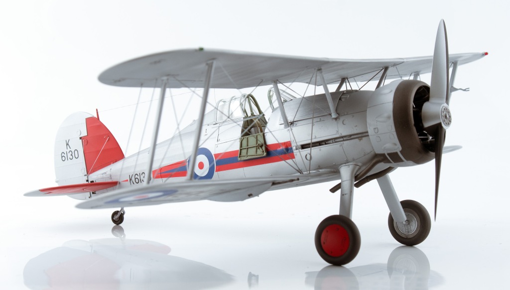
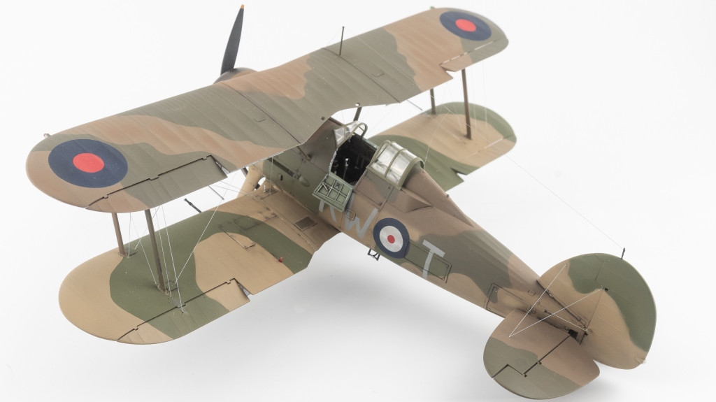
Gloster Gladiator Mk.I No.72 Sqn Royal Air Force Church Fenton. UK 1937
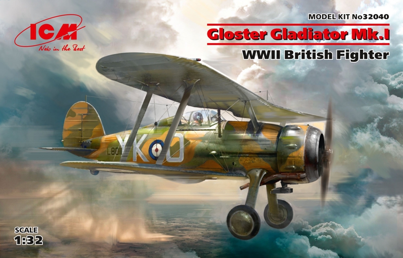
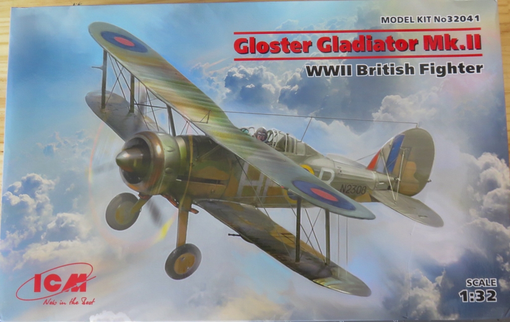
ICM released two boxings of the Gladiator. An initial Mk.I boxing followed by the Mk.II boxing a year later.
The MKII boxing being the one to get as it also contains all the MkI parts.
The kit is well moulded and comprises surprisingly few parts. This is the second ICM kit I have built, and they’ve both been very enjoyable build experiences, aided by good fit.
I was very much looking forward to starting this one too.
Construction Notes
Construction on this model started with the engine. No additions were used, it being built straight from the box. The completed engine looking quite busy to my eye. But spark plug leads could be added if desired, for a proper prototypical look. The join between the front collector ring and manifold should be filled, although this would be tricky to clean up, unless using a water based putty.
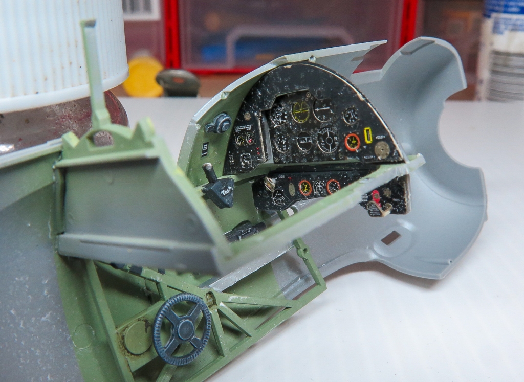
The breakdown of the cockpit gave me the initial impression ICM had greatly simplified it -true of every kit cockpit. But again upon completion and fitted, it looked suitably busy, especially if you enhance the Instrument panel with one of the 3d printed sets on the market, like Quinta, or as I used Yahu.
The throttle quadrant had two slots cut into it to accept the throttle and pitch control levers, and the rear of it was backed with some scrap card. The compass pedestal was replaced with the better detailed Quickboost item with the -in my case- out of register Yahu compass rose added to the face. The machine guns all had their barrels cut off, to be later replaced with brass barrels from Master Detail. The gunsight, part D19 also needs the reflector added from scrap clear plastic, a strange omission by ICM.
An example of how ICM have simplified the cockpit is Part C22, the rear shelf, which to be accurate should in fact, not be a shelf, but just the central beam. In the actual machine, you can see down into the fuselage either side. On the port side there is a TR9 radio , the face of which Yahu supplies in their set. Some photos show a rectangular box mounted to this frame that sits behind the pilots head. All this would be quite easy to replicate from scratch if the modeller so desired.
The very plain control stick really should be replaced with either a better detailed resin item, or detailed with sprue and scrap to better replicate the real thing. I just added a hand brake lever to mine, and left it at that
SMS British interior green was used, with a wash added from Modellers World ”wash for cockpit green.” Photos were conflicting on whether the cockpit was all green or green just above the sill with everything below silver. Mine was all grey green with a silver floor and seat. Once the prominent ejector pin mark in the seatback had been filled, seatbelts from HGW were added
With the cockpit added, the airframe built up fairly quickly, even with the added complication of cutting the flaps out and building up the AIMS PE flaps, which was achieved with some thin super glue applied with a bit of brass wire. The plastic flaps were cut from the kit wings with a thin PE saw after deepening the scribed lines so as to act as a guide for the saw.
Any gaps were filled with my super glue/metallic pigment mix. The underside insert needing a couple of passes before it was completely eradicated . There is no way those skinny little tailplane locating pegs are going to survive a knock, especially given ICMs soft plastic, so they were pinned to the fuselage with an old broken drill shank. The real machine having a gap between the tailplanes and fuselage. Whilst we have the brass rod out, the tail wheel should also have its locating peg replaced with the brass. This is another part that is prone to breakage, especially as ICM would have you fit it early in the construction process. All struts were left off until the painting was completed. Their fit to the wing is both positive and secure, so no problem adding them later. Same with the undercarriage, in hindsight, I wished I had of added it later as it made handling the model during the rigging process trickier. Whatever stage you add them, ensure you check the fit of the wheels to the axles. Mine were a little tight with the consequence that I broke an axle, which was sort of inevitable, given the soft plastic. The silver lining to this was it was repaired with a bit of brass wire that greatly increased its strength and also removed the flex from the plastic.
Painting and decaling
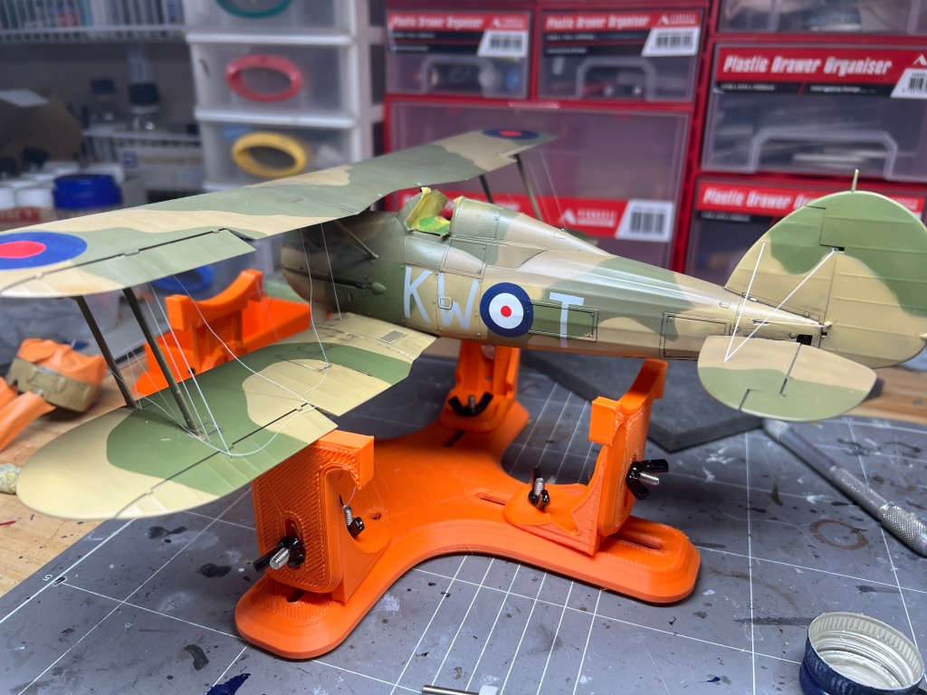
It took a great deal of studying photographs to decide on a scheme. The decision was complicated by the fact I wanted chosen scheme to feature black and white undersides , underwing roundels, early war type roundels and the four colour counter shaded scheme. If you think this would be an easy ask, think again! Early war Gladiators featured a multitude of schemes, sometimes, even in the same SQN. The Munich crisis roundels really appealed to me, but these aircraft were mostly silver undersides with no roundels. Eventually the 615 Sqn machine was picked, and to my joy, upon opening the 1 man Army mask set, roundels and codes for this very machine were included, saving me some Silhouette design time.
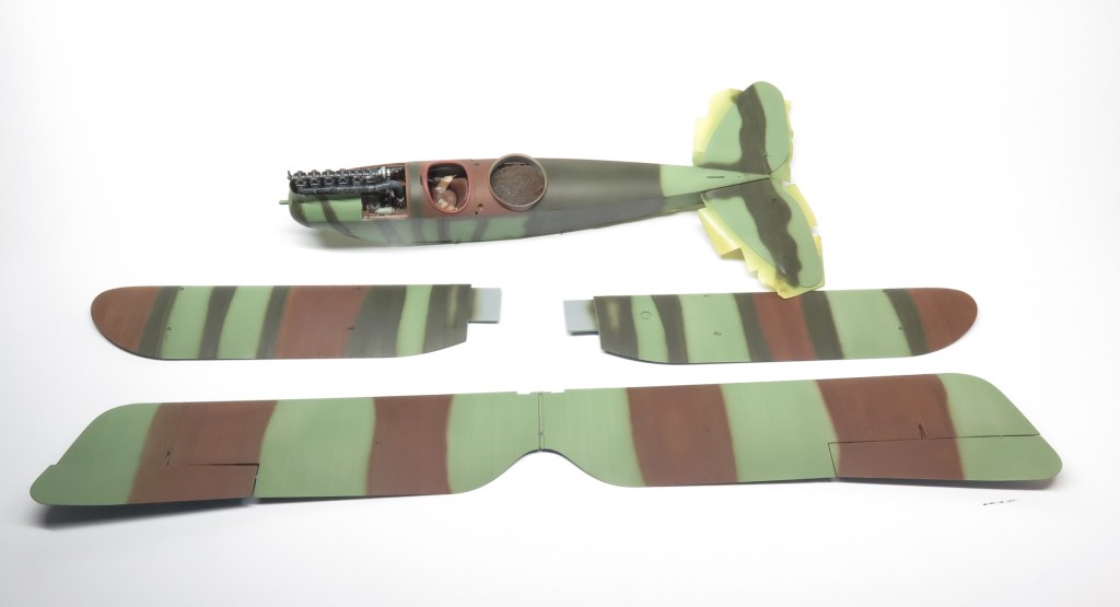
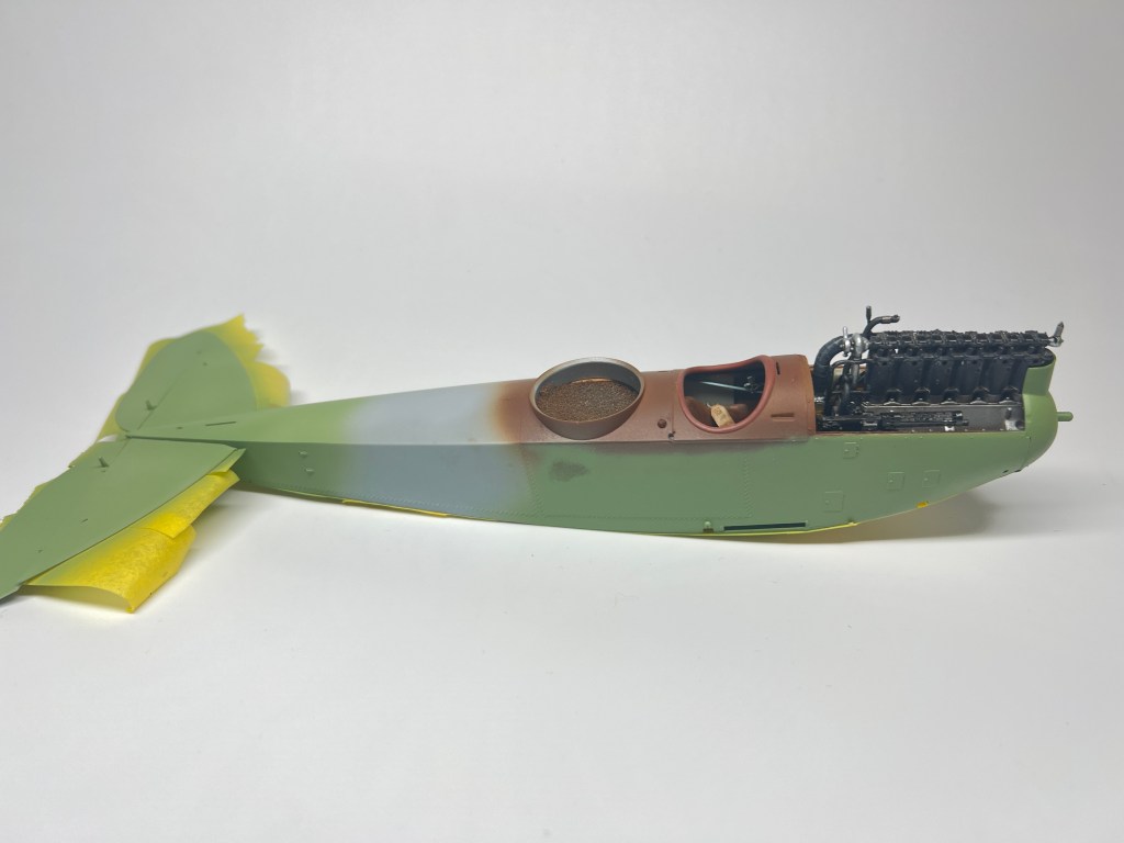
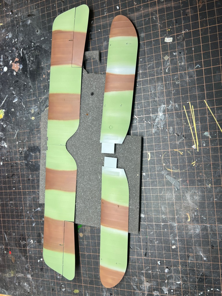
Painting started with the white half of the undersides using MRP white. The areas between the ribs were then sprayed with SMS German Cream and MRP Insignia white for some tone differences. The black half was base coated with SMS Camouflage black (my favourite black incidentally) and then the areas between the ribs were sprayed Tamiya rubber black. This was then masked off and a 50:50 mix of Gunze dark earth and MRP middle stone to represent the light earth was then sprayed on the top surfaces of the wings and lower fuselage. Tamiya RAF Green type 2 was mixed with a “smidge” of SMS Yellow for the light green. For painting the flying surfaces, TopNotch masks were used for the pattern, however the masks for the fuselage did not match the camouflage pattern of this particular aircraft , so blu tac sausages were used to mask the camouflage pattern.
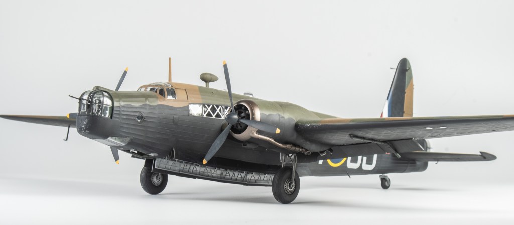
These machines had gone over to France camouflaged in the standard DE/DG camouflage in 1939, Whilst there, the newly developed counter shade scheme was applied, possibly around early 1940. I imagine it would not have been the neatest job, due the RAF having no large maintenance facilities in France. In any case Gladiators in France did not last too long, the SQN being re equipped with Hurricanes soon after.
The Dark Earth and Dark Green were Gunze colours subtly shaded with some lightened and darkened mixes.
There is no definitive proof what colours the wheel covers actually were. Both red and green being called out by various profiles and kit manufacturers. I went with green.. The white outline though is very clear from period photos.
MRP Medium sea grey was used for the codes, the roundel colours are tamiya Royal Blue and SMS red, the red at this stage of the war being the bright red.
Rigging
This was by far the most frustrating part of the build. Contrary to all those modelling articles stating how easy EZ line is to use. “Just add a drop of super glue into your pre drilled hole and the line pulls taut” my experience was anything but the simple, relaxing task all these articles and youtube videos make rigging out to be!.
First off, the CA, despite being a new bottle would not stick, not sure if it was the humidity, but you’d think that would help set it. This was after 10 interminable minutes first trying to get the EZ line to into my drilled hole! It seems if the EZ line even sniffs the presence of CA, it curls up, refusing to be poked into the hole. Poking the line into the unglued hole was easy enough, but then getting the CA glue onto your brass wire applicator and then apply it accurately into the hole. You need another two hands!
EZ line was used as I wanted to replicate the flat RAF wires, despite my best efforts, there are some twists in my rigging lines, and by this stage I’d lost all patience in going back and removing the twists. Anyway, for what its worth my method was to attach the various lengths of line into No.80 holes drilled into the top wing, which at this stage has not been attached to the model, ensuring that they would be aligned so as to give the flat effect of the real rigging.
The top wing was then attached and the lines cut to slightly shorter than the required length and fed into the pre drilled holes in the lower wing. This is where it all started to get pear shaped. Anyway, I persisted until all wires were added.
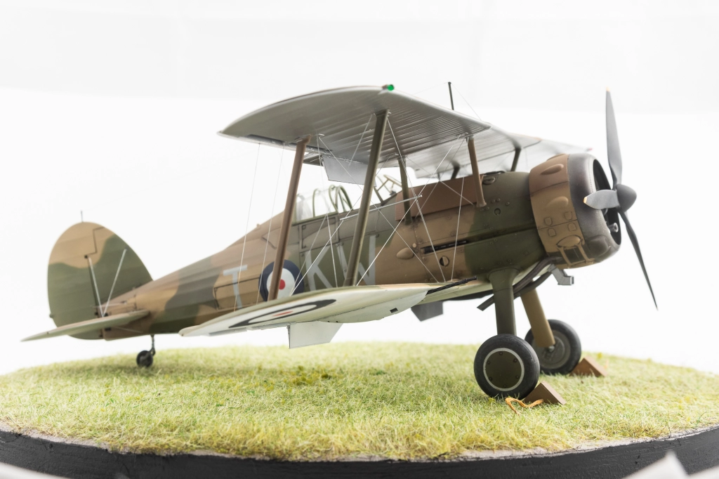
The eagle eyed most you will spot a gas patch white metal RAF terminal used on the lower wing to see how this looked. This was the only one used as I found it too hard trying to line up the others to the exact angle needed, the metal not being malleable at all. Finally it was all painted Vallejo steel. and the model just needed the canopies unmasking and she was done.
Well not quite done as I needed to add the antenna post as ICM don’t include one. Probably a blessing as any part supplied would probably not stand up to the pull of the EZ line that was used for the antenna wire. A mast was formed out of brass wire and glued to the starboard wing, not centrally as ICM show on their box art
CONCLUSION
I really enjoyed this build, so much so that I started the MkI that was still in the stash which was initially going to go on the for sale pile. ICM have done a lovely job on this model and delivered it in a scale which does the real aeroplane justice. There are some annoyances, the soft plastic being the main one as it really requires the modeller to replace the tailwheel and stabiliser mounts which otherwise are far too weak and prone to breakage. Other than that, I found the rigging very frustrating, but thats on me! Lots more practise needed before tackling all those Wingnut Wings kits in the stash, me thinks!
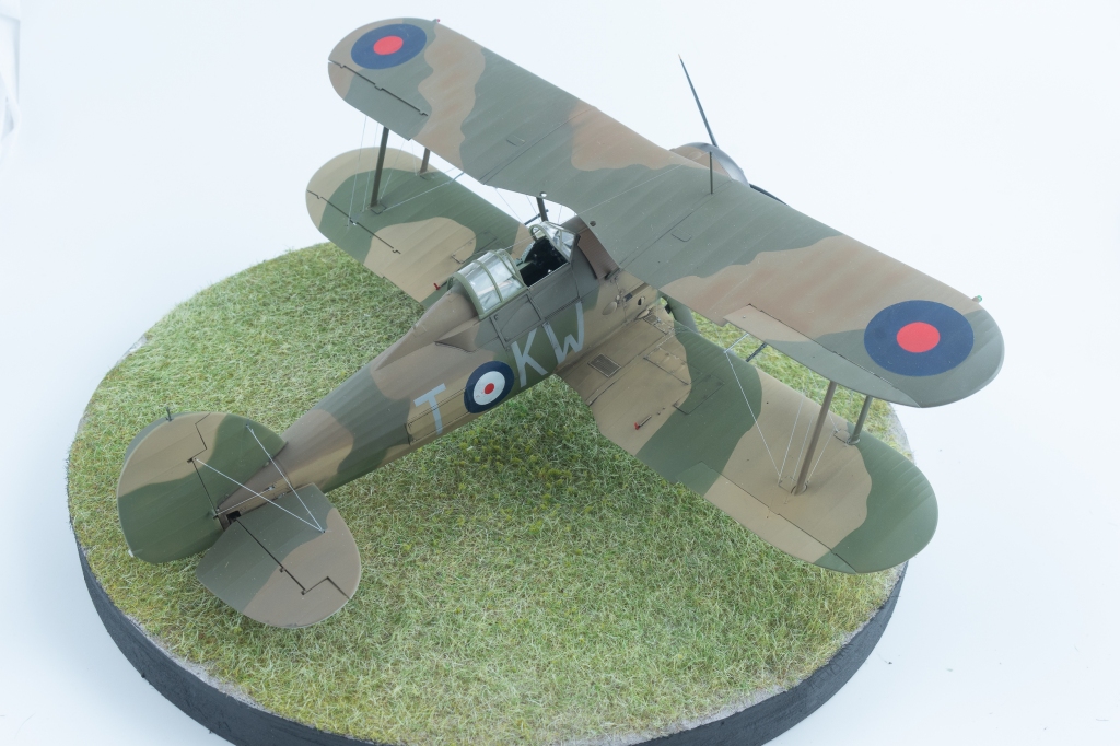
Gloster Gladiator MkII 615 SQN RAF St. Inglevert. France 1940
Paint: Xtracolour Dark sea grey, Dark slate grey, FAA sky grey
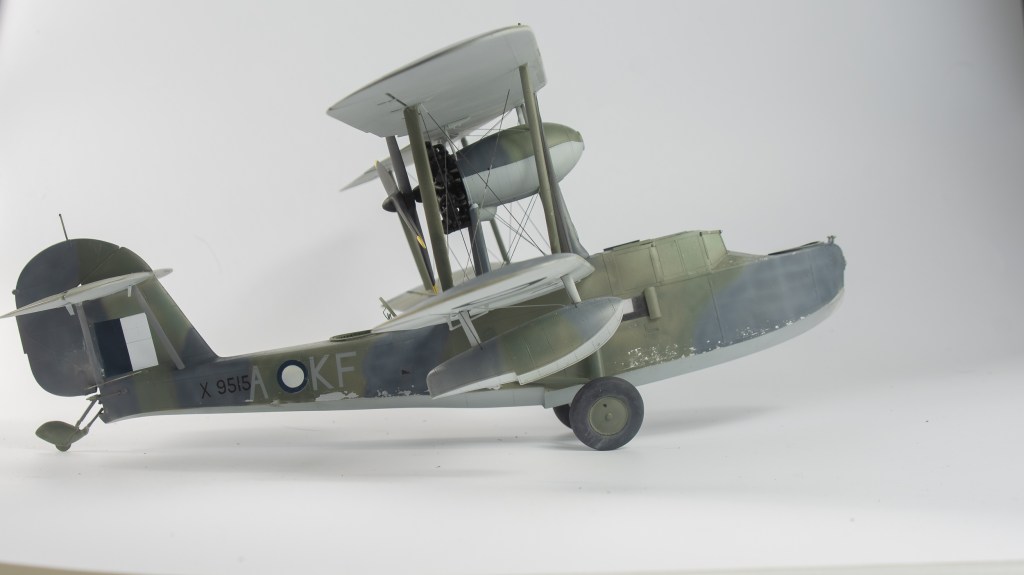
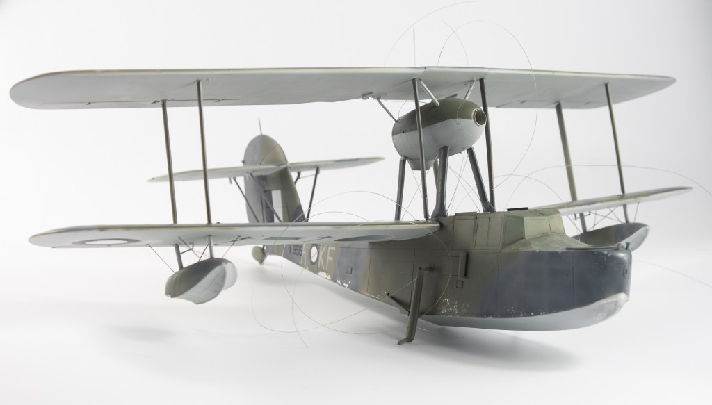
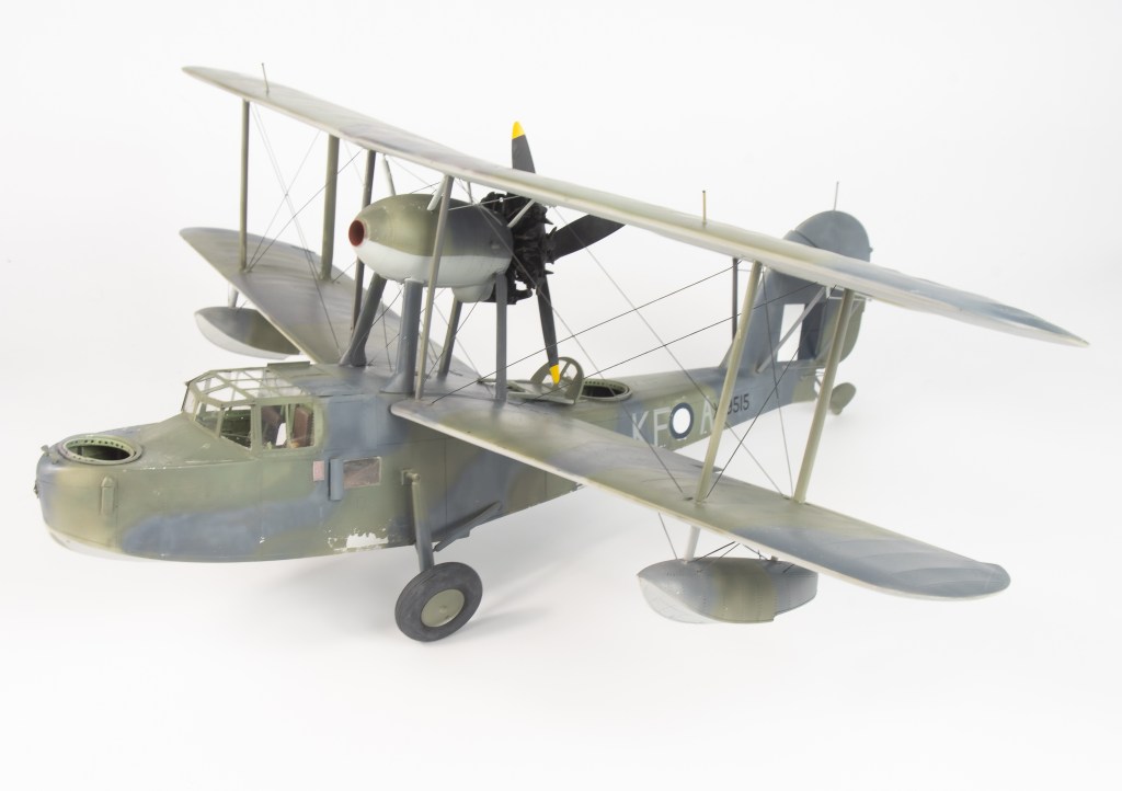
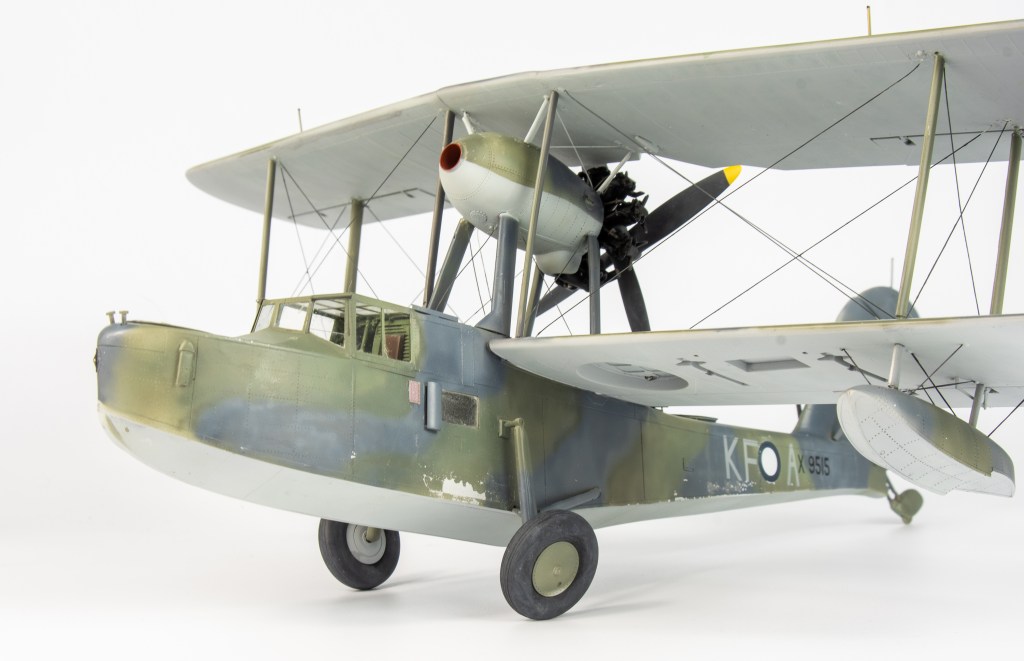
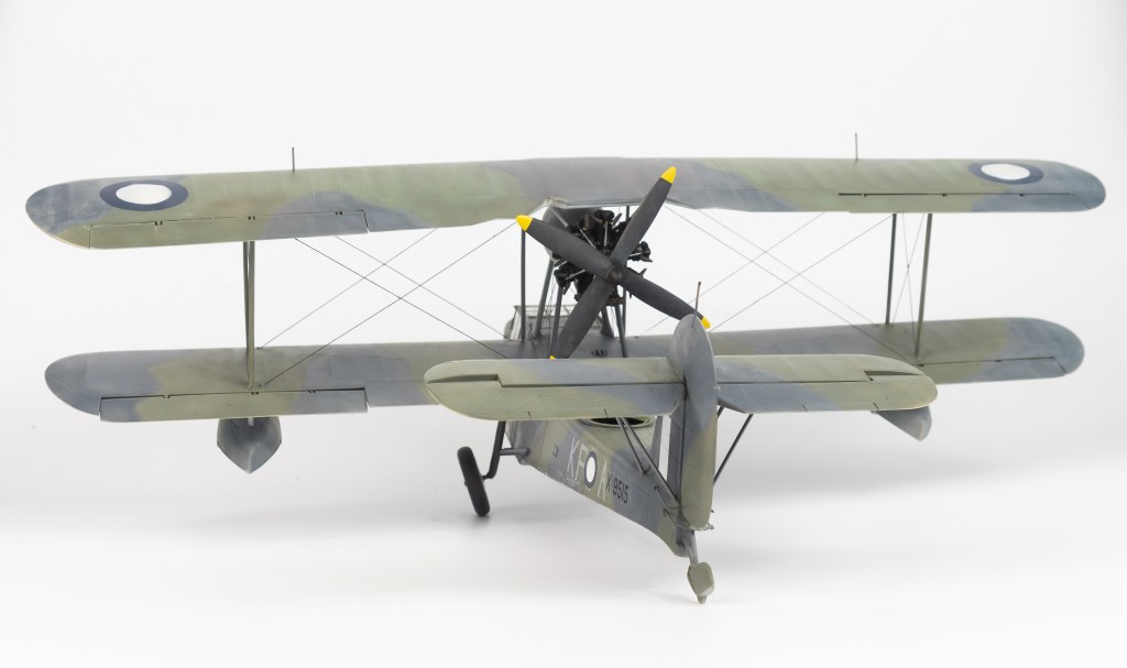
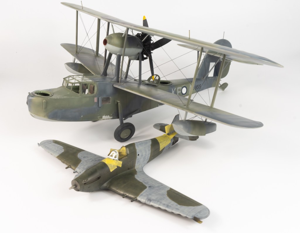
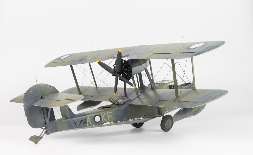
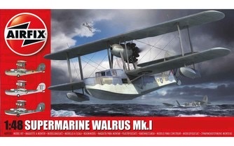
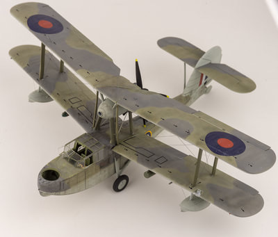
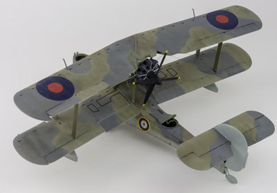
I had held off on getting Airfix’s new Walrus due to me having HPHs big resin 32 scale kit to build, however upon seeing a mate’s I just had to buy it. Not only that, I had to build it straight away! Airfix are really kicking goals with their new 48 scale kits, and this is no exception, with a fully riveted hull, stressed skin effect on the roof, a nice interior, and several options that allow you to model the wings folded or spread, canopies open or closed and wheels up or down The model assembled well with good fit. I found it a thoroughly enjoyable build, well, until I got to the rigging!
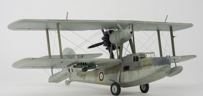
Painting was done with xtracolours and all was good until I got to the rigging. A combination of super glue that had gone off and would not instantly set and not really knowing what I was doing sort of bought the build undone. Still, I got their in the end, better equipped to handle that wingnut wings kit I want to tackle this year. Construction Notes Although there are plenty of injection moulding pins present on the interior surfaces, you cant see any, apart from two in the extreme nose once the fuselage is together. I elected to glue the roof to one side to better handle the joint as I could then attack it from both sides. Airfix have moulded some lovely surface detail into this kit so you want to reduce any need for sanding as much as possible The centre “fan looking thing” needs all traces of the moulding seam sanded off before glueing between the two engine nacelle halves I found the open cockpit a little too wide for the fuselage, although that could have been a fault on my part. Back to my kit. I found when on its wheels the folded wing float dragged on the ground due to me not securely glueing the wing spar. At the last minute I decided to cut the spar off and have both wings extended, This is the wing with the aileron deflected up. I could not debond the glue join unfortunately, so I will just have to live with it. An enjoyable kit, although the rigging turned it into a bit of a grind in the end.
Supermarine Walrus Mk1 700 N.A.S Royal Navy. H.M.S Sheffield


Leave a comment