- Purchased; 2019
- Built: 2024
- Enhancements:
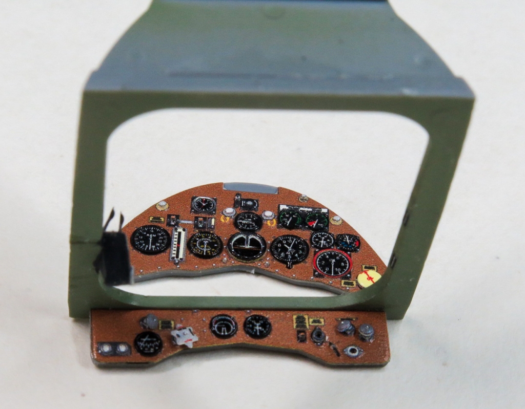
- Instrument panel: Quinta
- Seat Belts:Quinta
- Gun barrels; Master Details
- Cockpit Doors; Quickboost
- Air Breather pipes; Quickboost
- Compass Pedestal: Quickboost
- Decals: Aero craft Models
Introduction
I enjoyed my other Gladiator so much, I decided to build the second one in the stash rather than selling it as was the original intention.
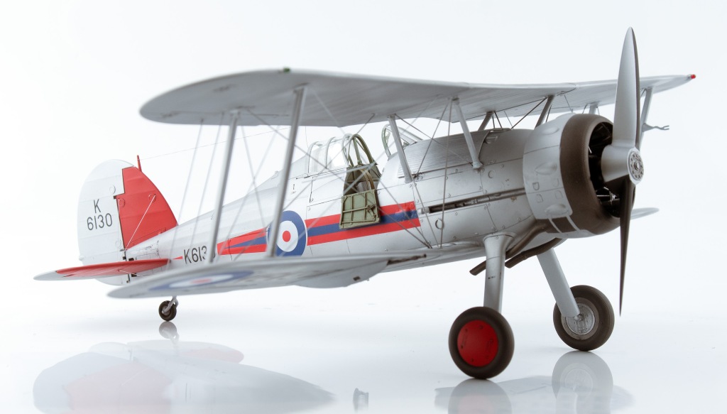
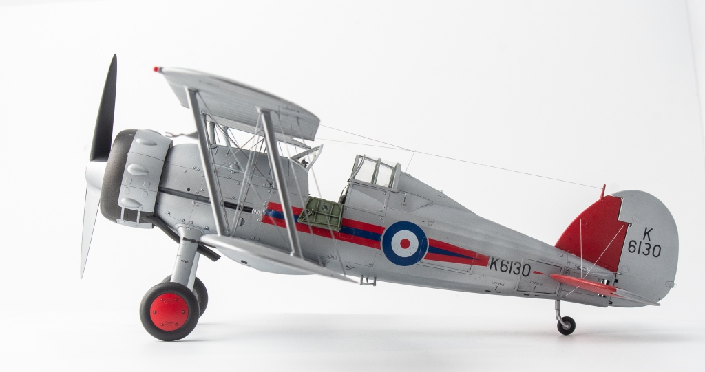
Even without considering the “foreign” air forces, such as Sweden or Finland one is spoilt for choice with Gladiator schemes, do you do a silver interwar one, or a camouflaged war RAF example? Then there are the Sea Gladiators as well. My previous model was finished in early war RAF camouflage, so this one would be a silver interwar RAF example.
Construction
To take a different path from the usual “starting with the cockpit”, the rudder, stabiliser and elevator halves were first glued together so that they would have time to properly set up and allow any glue shrinkage to show itself.
With this done, construction returned to following the steps outlined in ICMs instructions, starting with the cockpit. ICM provides parts that when built up result in a reasonably busy looking cockpit.
Of course, the builder can improve on this. In my case I included some simple additions and refinements starting off with wrapping thin copper wire around the spade grip of the very plain looking control column. A brake lever, cam and the brake line were added from scrap plastic and solder.
Map cases were built up out of plastic card, and the slots on the throttle quadrant deepened with a Trumpeter scriber before new throttle levers were added from slivers of plastic card topped with blobs of paint.
Quinta 3D Decals were used to replace the instrument panels and seatbelts. The kit compass pedestal was replaced with a better detailed Quickboost item.
There is an ejector pin in the seatback that needs to be filled and the gunsight requires the clear reticule adding. A punched disc of clear plastic did the job here.
Once the cockpit shelf is added, you really can’t see too much into the depths of the cockpit, even with the cockpit access doors opened. Speaking of shelves, to better replicate the real item, the rear shelf behind the pilot (part C22) was cut down to leave just the central beam. To my eye, this really adds to the open framework look of these 30’s era aircraft.
If you wanted to add detail to the now visible interior behind the pilots seat, frames and a radio could be built up from card and strip. I didn’t bother as my canopy will be open and sitting over the top of the fixed canopy section, so hopefully, that empty space will not be too visible. Finally, the machine gun barrels were cut off, as these would be replaced by brass Master Detail barrels once all painting had been completed.
With the cockpit painted and detailed to my satisfaction, the fuselage halves could now be closed. This was achieved with Tamiya Extra Thin Glue which was liberally applied allowing the excess to ooze out to fill any gaps.
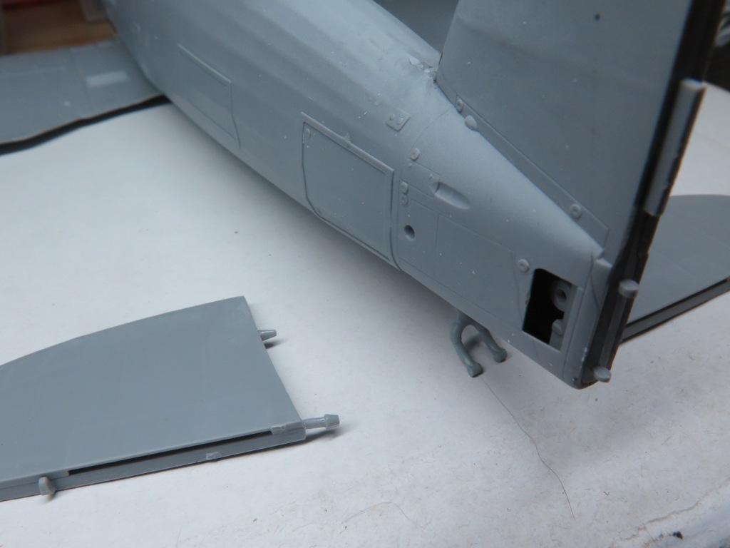
The two halves fit tightly. The lower insert…..not so much. That said the gaps here were minor and were eradicated with CA glue mixed with Mig Ammo Steel metallic pigment. To me the pigment seems to make the CA slightly easier to sand and also has the benefit of colouring the glue so you can see what you are sanding!
The fuselage was then mated to the lower wing assembly with some filler required to blend in the rear join. A result of the soft ICM plastic the wings are alarmingly flexible but adding the struts and top wing will hopefully add some rigidity.
ICM would have you rely on a small diameter plastic peg, inserted into a hole in the fuselage to hold the horizontal stabilisers in place. Given the soft plastic, this would likely end in tears so the pegs were cut off and a suitable diameter brass rod used to provide far more strength. Even more fortuitous is that the real Gladiator has a small gap here between the fuselage and stabiliser. While you have the brass rod out, the tailwheel strut can also be cut and replaced as this is another weak area of the model.


With this done, a complete airframe and top wing sat on my bench awaiting primer. Prior to priming, a No. 77 drill was used to open up all the rigging points as I intended to use EZ line for the rigging. Once all holes were drilled, the struts were cleaned up and attached in their respective positions.
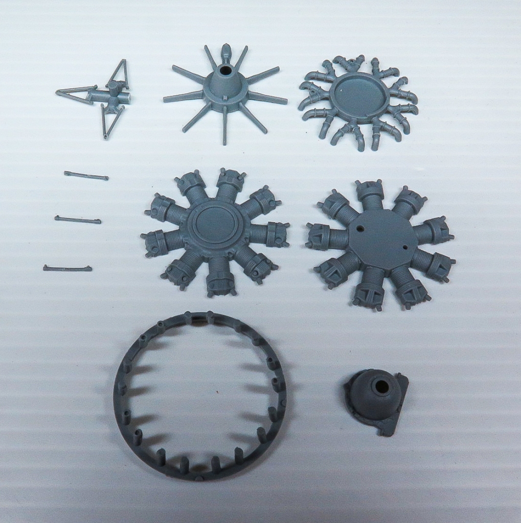
Next up was the engine. Again, ICM have done an excellent job of portraying the Mercury engine. When completed it looks quite busy with its cowling support braces and cooler intake tubes. Quickboost do make one piece air cooler intake tubes that are slightly better detailed however I didn’t use them on my model as the kit ones looked fine to my eyes. The instructions here were slightly confusing, but eventually I worked out you have the option of building the cowling closed or open. If building the closed version, do not add the cylinder heads, parts D14 or exhaust pipe “plates parts D21 and D22.
In a perfect illustration of the pre planning that goes into all my models, it was now that I decided the model would look better rigged with the AIMS PE Bracing wire set rather than the EZ line. The reasoning being that the PE would better represent the flat RAF wires that were used on the real aeroplane. The set was promptly ordered from AIMS in Hungary. Post from Hungary to Australia takes about three weeks.
Painting and Finishing
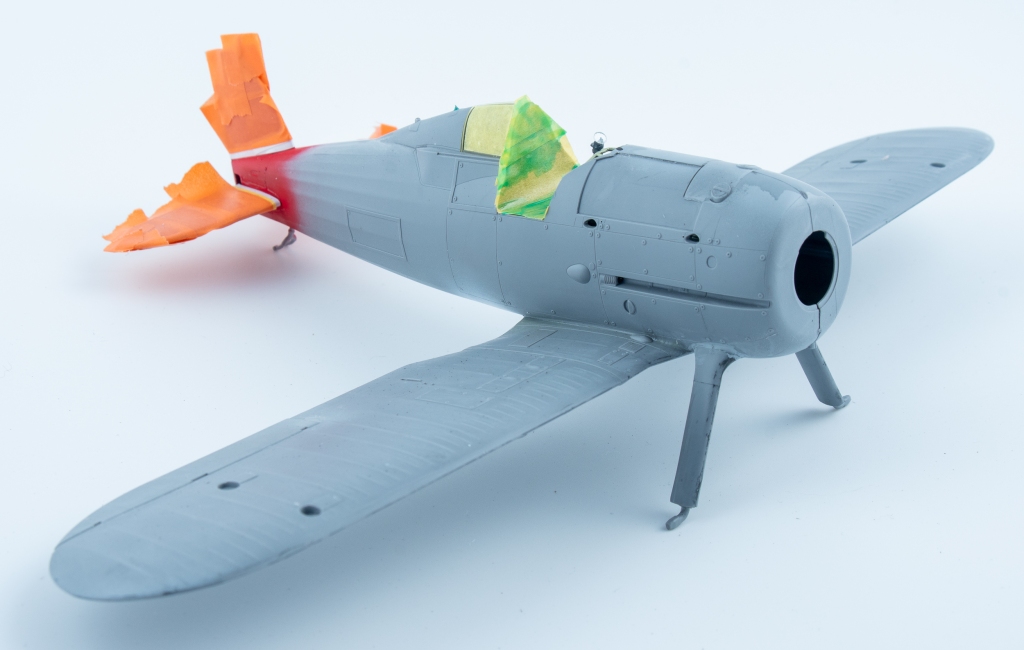
While waiting for the PE bracing to arrive the model was painted. A primer coat of Mr Surfacer 1500 revealed a few seams, mainly around the lower fuselage insert. These were eventually dealt with, some which required multiple attempts!
The fixed tail surfaces and wheel hubs were then given several light coats of SMS red. This was then masked off and the remaining airframe, tail control surfaces and cowling got the Tamiya LP11 treatment with the model being rubbed down with fine 8000 grit sanding pads between coats.
Once the AIMS rigging arrived a careful perusal of the instructions revealed that AIMS wants you to remove the moulded inspection hatches from the wings so that they can be replaced with PE items. The idea being that the hatches are placed over half the hole drilled for the rigging to make a slot for the PE bracing wires.
Whilst the AIMS instructions provide clear photos of an actual Gladiator to assist you with placing the PE bracing wires, it would have been more useful to have been given precise measurements as to where to drill the holes to accept the wires. Of course, this meant that some of my previously drilled holes were in the wrong spot so these were carefully filled and redrilled all the time dodging previously installed struts.
In the end it all looked a bit messy, so the decision was made to strip the model using Mr Thinner and repaint. This took me back to where I was 3 weeks prior. I would complete far more models each year if I didn’t have to do so much twice or three times to each model!
On the other Gladiator build I had used a 1 Man Army mask set for the stencils and these had really impressed me sot they were put to work again. If you have not seen these sets, they are laser cut masks for not only the national markings, but also all the maintenance stencils. As the surrounding area needs to be taped off to prevent overspray, all these markings were sprayed prior to applying the decals as I did not want to be applying Tamiya tape over decals. SMS Super matt Black was used to spray all the stencils, and then the masks removed.
The decals are by Aerocraft Models. These performed very well, laying down with the aid of Microset and Microsol. However, (there’s always a however!) Aerocraft do not give you handed fuselage Sqn flashes.
Both flashes provided are for the port side fuselage. To apply the flash correctly to the starboard side and have the serial read correctly, the modeller will need to cut the serial from the flash and apply it separately so it is correctly orientated. If applied straight off the sheet without modification your serial on one side will be upside down and back to front.
The front of the stripe is also angled to follow the panel line there, and if not corrected, this will slope the wrong way also. Aerocraft helpfully supply some spare striping in both red and blue, and this was used to reverse the angle of the flash on that side.
A sealing coat of SMS flat varnish was then applied over the whole model. Once dry, panel lines were given a wash using Tamiya dark grey panel line accent with the excess being wiped off using white spirits. Removable panels were outlined with black wash.
I wanted something different from my usual weathered finishes so on this model I went with a cleaner finish.
The exhaust collector ring and exhaust pipes were painted in a mix of MRP Exhaust Colour and SMS Dark Bronze. If using the kit exhaust pipes, they will need their ends drilled out.
The Master Details machine gun barrels were first sprayed with Mr Metal Primer, followed by a coat of Tamiya Semi-Gloss Black with a final coat of Humbrol Gunmetal. This was then gently buffed for about 20 minutes which imparted a lovely metallic sheen.
Rigging
The rigging could now be attended to using the AIMS set. All started well with the crossed cabane wires and inboard wires working as advertised. Turning to the tail, despite drilling the holes as called out in the instructions, I just could not get the AIMS wires to fit. AIMS only provide measurements for the holes in the tailplanes. I really wish they had supplied all measurements.
Of course, a better modeller than me would probably have measured the wires against their respective positions before drilling. As a consequence, the interplane wires were far too short to span between the holes I had drilled so EZ line was used for the rigging. EZ Line was also used for the tailplanes. In all, only the cabane rigging was used from the AIMS set. Other people have used this set without drama, so the inability to get a good result using it was purely my doing.
Final Steps
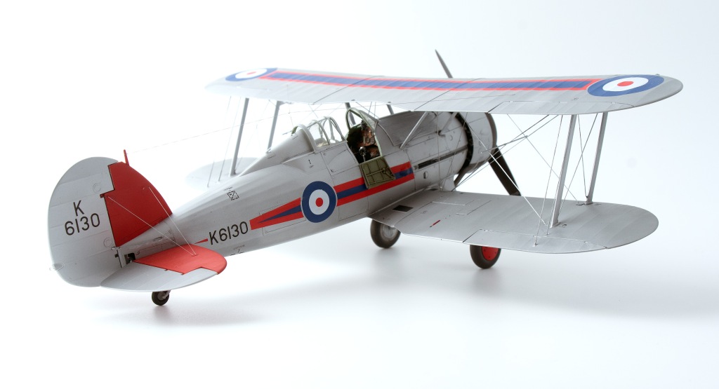
On the final stretch the wheels were added. Then the model was given another coat of SMS Flat varnish, which dulled the silver nicely, making it look more like doped silver.
The clear parts were then unmasked and the gun barrels added.
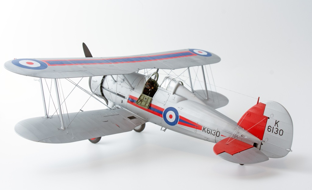
The aerial wire on these early machines extended from the tail fin post to a point just behind the canopy where it then split into two wires reaching out to each wing. To portray this, first a length of EZ line was added stretching span wise across the wing. Next, another length was glued to the fin post with its other end intersecting the wing line. Tension was then taken up so that the wing line stretched into a V, meeting the fuselage wire at a point over the spine. A couple of turns around the wing wire were added and then a drop of Superglue was added to the fuselage wire to keep it all in place.
Finally, a length of monofilament thread was run from behind the cockpit up to meet the junction of all these wires. Small dabs of Vallejo matt varnish were brushed over the superglue to remove any shininess and the model was done.
Conclusion
I found the ICM Gladiator an enjoyable build, to the point this is the second one I have completed.
Only a minimum of aftermarket enhancements were added to enhance certain details. In my opinion there is enough detail out of the box to satisfy most modellers, what is there providing an excellent base for further detailing and refining if that’s your thing.
For me, the machine gun barrels, seat belts and instrument panel were “must have” refinements. To this I would add the Quickboost cockpit doors, exhaust pipes, and if doing a MKII, the carburettor intake as “seriously think about getting”.
The AIMS bracing wires did not work FOR ME, but I do think they would enhance the finished model nicely being the proper flat section wire.
Weak points (literally) of the model were the stabiliser and tailwheel mounting points due to the ICM soft plastic.
Gloster Gladiator Mk.I No.72 Sqn Royal Air Force Church Fenton. UK 1937


Leave a comment